Gripper bar with swinging device and operating method thereof

A technology of a swinging device and a working method, which is applied in the field of tooth rows, can solve the problems of increased manufacturing cost and maintenance cost, difficult operation by workers, many connecting parts, etc., and achieves the advantages of shortened downtime frequency and downtime, comfortable operation and strong flexibility. Effect

Active Publication Date: 2009-09-02
MASTERWORK GROUP CO LTD
View PDF1 Cites 9 Cited by
  • Summary
  • Abstract
  • Description
  • Claims
  • Application Information

AI Technical Summary

Problems solved by technology

The connecting parts are very numerous and complicated, occupy a lot of space, virtually increa

Method used


Image

  • Gripper bar with swinging device and operating method thereof
  • Gripper bar with swinging device and operating method thereof
  • Gripper bar with swinging device and operating method thereof

Examples


Embodiment

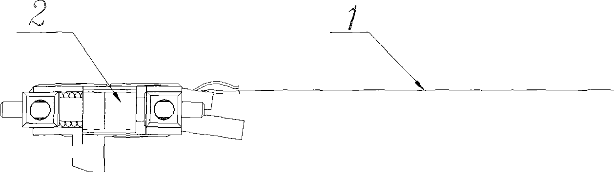
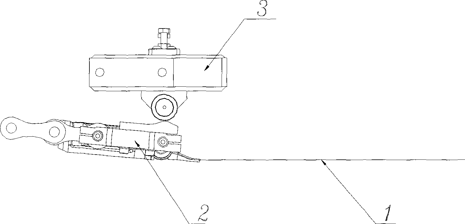
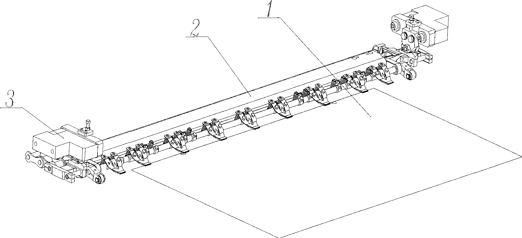
[0024] Embodiment: a kind of row of teeth that swing device is arranged (see figure 2 , image 3 ), including tooth row 2, is characterized in that it also includes cam follower mechanism 3 and cam block 3-5; Wherein cam follower mechanism 3 is installed on the wallboard of working position; Said cam block is installed on the tooth row 2, and corresponding to the cam follower 3, the highest position of the cam block 3-5 is consistent with the center of the cam follower 3.

[0025] The above-mentioned cam follower mechanism 3 is symmetrically installed on both side wallboards of the working position. (See image 3 )

[0026] The above-mentioned cam blocks 3-5 are symmetrically installed on both sides of the tooth row 2 . (See image 3 )

[0027] The above-mentioned cam follower mechanism 3 (see Figure 4 ) includes a support block 3-1, an adjustment fixed plate 3-2, an adjustment block 3-3, a fixed seat 3-4 and a cam follower bearing 3-6; wherein the support block 3-1 i...


PUM


Abstract

The invention discloses a gripper bar with a swinging device, which comprises a gripper bar and is characterized by also comprising a cam follower mechanism and a cam bit. The operating method comprisThe invention discloses a gripper bar with a swinging device, which comprises a gripper bar and is characterized by also comprising a cam follower mechanism and a cam bit. The operating method comprises the following steps that: (1) the cam follower mechanism is symmetrically fixed on two side wall plates at an operating position; (2) the cam bit is symmetrically fixed on upper planes on two sideses the following steps that: (1) the cam follower mechanism is symmetrically fixed on two side wall plates at an operating position; (2) the cam bit is symmetrically fixed on upper planes on two sidesof the gripper bar; (3) the gripper bar grips paper and starts swinging up and down; (4) the gripper bar swings downward to the lowest point; and (5) the gripper bar swings upward with the curve of t of the gripper bar; (3) the gripper bar grips paper and starts swinging up and down; (4) the gripper bar swings downward to the lowest point; and (5) the gripper bar swings upward with the curve of the cam bits to return to the original position to complete one swing period. The method has the advantages that: the least number of parts are required for realizing the action and functional requiremhe cam bits to return to the original position to complete one swing period. The method has the advantages that: the least number of parts are required for realizing the action and functional requirement of smoothly and stably attaching paper gripped by the gripper bar onto a stripping plate; and the stripping frame is fixed and a large number of transmission pieces and connecting pieces are savedent of smoothly and stably attaching paper gripped by the gripper bar onto a stripping plate; and the stripping frame is fixed and a large number of transmission pieces and connecting pieces are saved, so the manufacturing cost and maintenance difficulty are reduced and space is saved and the operation of operators are facilitated. The gripper bar and the working method thereof are applicable to s, so the manufacturing cost and maintenance difficulty are reduced and space is saved and the operation of operators are facilitated. The gripper bar and the working method thereof are applicable to single or multi-unit platen oil stamping and die cutting machines.ingle or multi-unit platen oil stamping and die cutting machines.

Description

(1) Technical field: [0001] The invention relates to a device suitable for printing machinery and its working method, in particular to a tooth row with a swing device and its working method. (two) background technology: [0002] Enterprise competition is becoming more and more fierce, improving equipment precision and reducing equipment manufacturing costs are the goals pursued by every manufacturer. It is also a magic weapon for enterprises to remain invincible. [0003] prior art (see figure 1 ) mainly includes: paper 1, tooth row 2. In the prior art, the jaws 2 generally use the grippers to move to each working position. The jaws do not swing downward during the whole process. When the paper needs to be put down, a large number of mechanisms have to be driven by power to complete its function. Although it can also complete the required However, the large structure increases the cost, takes up a lot of space, makes maintenance difficult, and the operation is cumbersome,...

Claims


Application Information

Patent Timeline
IPC IPC(8): B41F21/04B65H5/08
Inventor 王玉信韦树远首云飞
Owner MASTERWORK GROUP CO LTD
Why Eureka
Try Eureka