
Underground state determination method and device and state control method and device

A state and overflow state technology, which is used in the determination of downhole state, natural gas drilling safety, and oil fields. Ensuring accuracy and improving latency

Inactive Publication Date: 2015-04-22
BC P INC CHINA NAT PETROLEUM CORP +1
View PDF7 Cites 12 Cited by
  • Summary
  • Abstract
  • Description
  • Claims
  • Application Information

AI Technical Summary

Problems solved by technology

[0005] However, the traditional observation method has its limitations, and sometimes it is impossible to correctly judge the downhole situation. For example, the drop in the pressure of the wellhead standpipe may be caused by the puncture of the drilling tool; the increase in the pressure of the standpipe may be caused by the blockage of the water hole of the drill bit, and the circulation system cannot be carried out normally. due to
In addition, using traditional observation methods, when overflow or leakage is found, the amount of overflow or leakage is often already large, and the time left to deal with the accident is already short, which can easily lead to major accidents

Method used


Image

  • Underground state determination method and device and state control method and device
  • Underground state determination method and device and state control method and device
  • Underground state determination method and device and state control method and device

Examples


Embodiment Construction

[0032] The following will clearly and completely describe the technical solutions in the embodiments of the present invention with reference to the accompanying drawings in the embodiments of the present invention. Obviously, the described embodiments are only some, not all, embodiments of the present invention. Based on the embodiments of the present invention, all other embodiments obtained by persons of ordinary skill in the art without making creative efforts belong to the protection scope of the present invention.

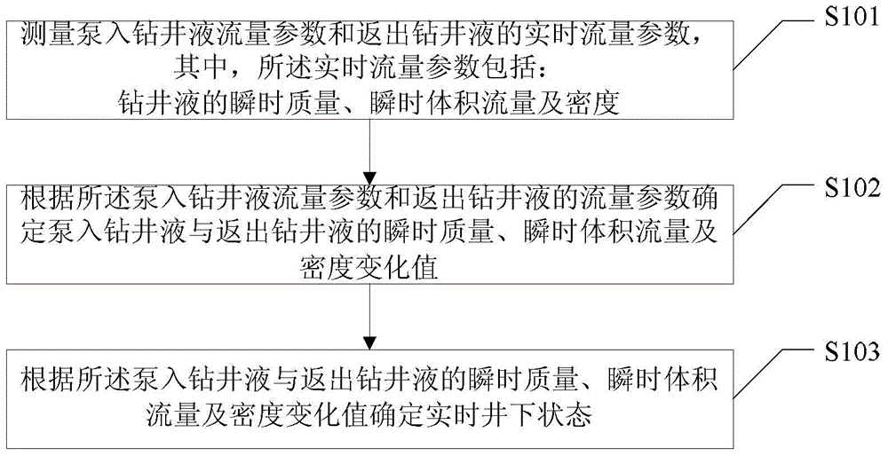
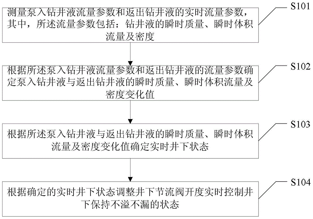
[0033] Such as figure 1 As shown, the present invention provides a method for determining the downhole state. The downhole state includes: an overflow state, a leakage state and a non-spill and non-leakage state. The method includes:

[0034] Step S101, collect the flow parameters of the pumped drilling fluid and the real-time flow parameters of the returned drilling fluid, wherein the real-time flow parameters include: the instantaneous mass, instantaneous vo...


PUM


Abstract

The invention provides an underground state determination method and device and a state control method and device. The underground state comprises an overflow state, a leakage state and a non-overflow and non-leakage state. The underground state determination method comprises collecting pumped drilling liquid flow parameters and real-time flow parameters of the returned drilling liquid, wherein the real-time flow parameters comprise the instantaneous quality, the instantaneous volume flow and the density of the drilling liquid; determining the instantaneous quality, the instantaneous volume flow and density change values of the pumped drilling liquid and the returned drilling liquid according to the pumped drilling liquid flow parameters and the flow parameters of the returned drilling liquid; determining the real-time underground state according to the instantaneous quality, the instantaneous volume flow and the density change values of the pumped drilling liquid and the returned drilling liquid. According to the underground state determination method and device and the state control method and device, the three parameter methods are matched with each other, meanwhile the influence of the time is considered, the instantaneous analysis, the static correction and the long time observation are performed on the parameters, and accordingly the accuracy of the judgment result can be ensured.

Description

technical field [0001] The invention relates to the field of petroleum and natural gas exploration, in particular to oil and natural gas drilling safety technology, specifically a method and device for determining the downhole state, and a state control method and device. Background technique [0002] In the process of drilling, overflow and loss are complex situations that are often encountered. Among them, leakage refers to a downhole complex situation in which drilling fluid leaks into the formation during drilling; overflow is the opposite of leakage, which refers to the A downhole complex situation in which formation fluid flows into the wellbore during the process. [0003] The two complex situations of overflow and leakage will cause serious consequences if they cannot be detected and controlled in time. The leakage will lead to the loss of a large amount of valuable drilling fluid, which will affect the normal drilling work and cause the pressure of the fluid column ...

Claims


Application Information

Patent Timeline
IPC IPC(8): E21B49/08E21B47/00
CPCE21B47/10
Inventor 姜英健滕学清刘伟朱金智周英操李宁王瑛文志明王倩郭庆丰王凯马鹏鹏张兴全崔堂波
Owner BC P INC CHINA NAT PETROLEUM CORP
Learn More