

Vibration active control testbed
An active control, test-bed technology, applied in vibration testing, testing of machine/structural components, measuring devices, etc., can solve problems such as insufficient flexibility and cost control, complicated operation of MTS equipment, and bulky three-phase synchronous motors, etc. To achieve the effect of intuitive effect, low cost and low manufacturing cost
- Summary
- Abstract
- Description
- Claims
- Application Information
AI Technical Summary
Problems solved by technology
Method used
Image

Examples
Embodiment Construction
[0024] The present invention will be described in detail below in conjunction with the embodiments of the accompanying drawings. Wherein the same components are denoted by the same reference numerals. It should be noted that the words "front", "rear", "left", "right", "upper" and "lower" used in the following description refer to the directions in the drawings, and the words "inner" and "outer ” refer to directions towards or away from the geometric center of a particular part, respectively.
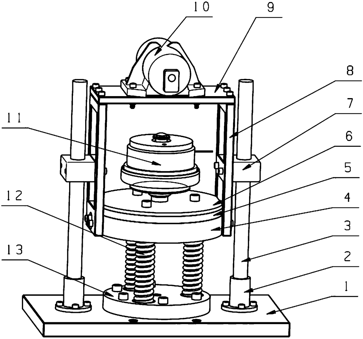
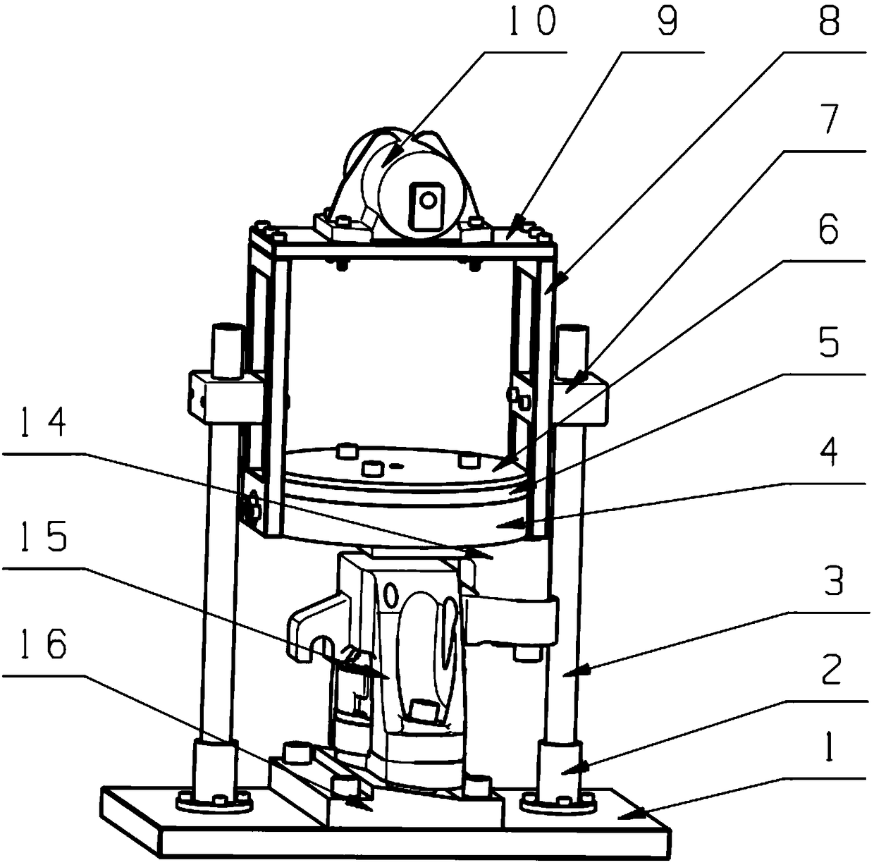
[0025] Such as figure 1 As described above, an active vibration control test bench includes a bottom plate 1, two optical axes 3 symmetrically and vertically fixed on the bottom plate 1, a door-shaped bracket located between the two optical axes 3, and a door-shaped bracket fixed on the door-shaped An adjustable motor vibration device at the top of the bracket, sliding bearings 7 sliding up and down along the optical axis are respectively fixed in the middle of the two outer sides of t...
PUM
 Abstract
Description
Claims
Application Information