Method for controlling strip-steel head and tail temperature

Active Publication Date: 2009-09-02
BAOSHAN IRON & STEEL CO LTD +1
View PDF0 Cites 15 Cited by
  • Summary
  • Abstract
  • Description
  • Claims
  • Application Information

AI Technical Summary

Problems solved by technology

If the thickness of the front and rear steel coils changes, the temperature of the transition part of the weld must fluctuate, even exceeding the annealing temperature range required by the process, resulting in large fluctuations in the performance of the transition part or unqualified

Method used


Image

  • Method for controlling strip-steel head and tail temperature
  • Method for controlling strip-steel head and tail temperature
  • Method for controlling strip-steel head and tail temperature

Examples


Embodiment Construction

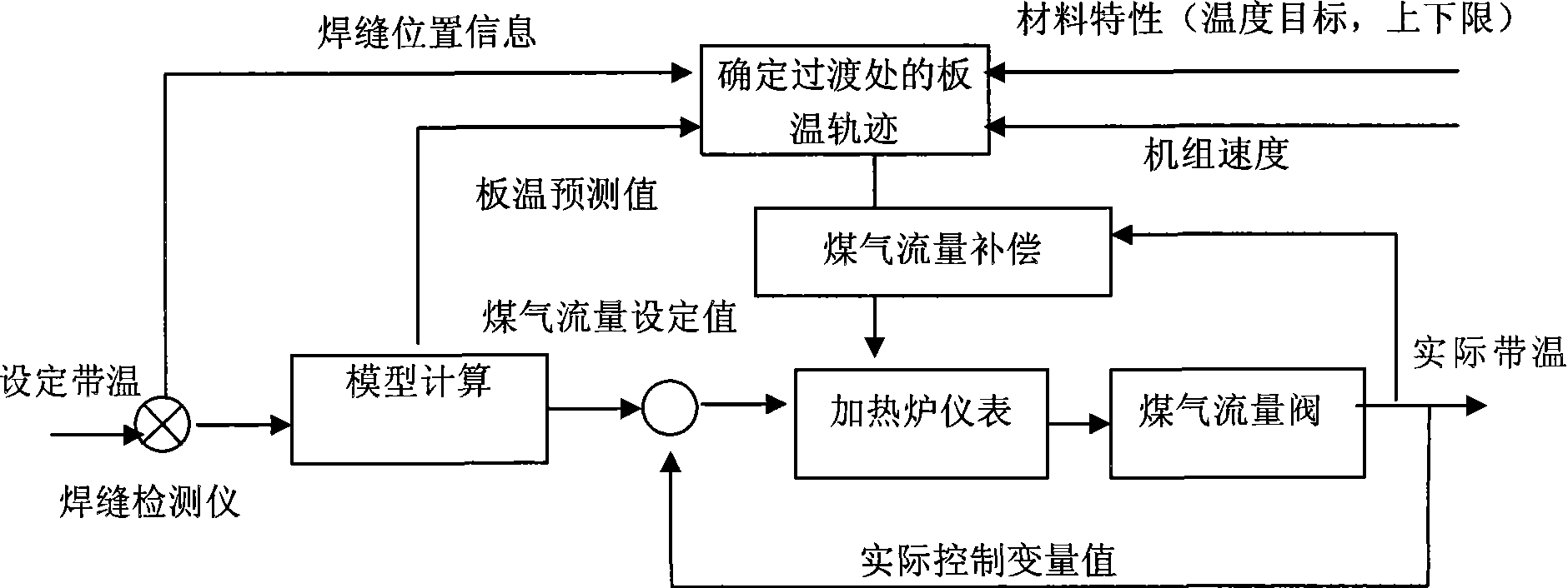
[0054] Such as image 3 , as shown in 4:

[0055] A. Use the weld detector to detect the strip weld within a certain distance before the next strip enters the heating furnace.

[0056] B. Using a mathematical model, calculate the predicted value Tout of the plate temperature of the strip steel at the exit of the heating furnace and the change of the plate temperature. The mathematical calculation formula:

[0057] Tout={TF-TSi} SVF+TSi

[0058] SVF ≡ Tout - TSi TF - TSi = 1 - exp [ - 1 s 1 ( TV - TVave ) + s 2 ...


PUM


Abstract

The invention discloses a method for controlling strip-steel head and tail temperature, comprising the following steps of: A. detecting positions of welded seams of strip-steels by a detector; B. calculating predicted strip temperature values of the front and the back strip-steels at a heating furnace outlet by a mathematical model to obtain a strip temperature variation between the front and the back strip-steels; C. taking the strip temperature variation into consideration and ascertaining target strip temperatures of the upper and the lower strip-steels at the positions of the welded seams according to a principle that the predicated strip temperature values at the tail of the upper strip-steel coil and at the head of the lower strip-steel coil are not lower than a lowest annealing temperature required by the strip-steels; D. according to the obtained target strip temperatures, utilizing an empirical formula for the temperature-rise period of the heating furnace to fix the locus of the target strip temperature at the welded positions; E. according to the difference between the locus of the target strip temperature and the predicated strip temperature values, calculating a gas flow compensation value; F. counting up the gas flow compensation value and a gas flow set value calculated by the model and transmitting the total value to a heating furnace meter; and G. controlling the openness of a gas valve by the heating furnace meter through a loop.

Description

technical field [0001] The invention relates to a method for controlling the temperature at the head and tail of a steel strip, in particular to a method for controlling the temperature at the head and tail of a steel strip used in a cold rolling continuous annealing production line. Background technique [0002] The general situation of the heating furnace of the continuous annealing unit is as follows: figure 1 As shown, gas heating is used, steel coils of different thicknesses and widths are welded to achieve continuous pass-through in the heating furnace, and annealing is carried out according to the target temperature (which can fluctuate within the upper and lower limits) required by the process to meet the mechanical properties of the product. . [0003] The control of the heating furnace of the continuous annealing unit is divided into furnace temperature control and belt temperature control. The furnace temperature control model aims to control the actual furnace ...

Claims


Application Information

Patent Timeline
Patent Type & Authority Applications(China)
IPC IPC(8): C22C1/00
Inventor 何建锋林莉军
Owner BAOSHAN IRON & STEEL CO LTD
Why Eureka
Try Eureka