
Automatic degassing and oil changing device

An automatic and oil-drum technology, applied in the direction of transformer/inductor cooling, etc., can solve problems such as difficult to guarantee airtightness, error-prone, emergency shutdown, etc., to achieve equipment safety, airtightness, and airtightness sex guaranteed effect

Active Publication Date: 2011-06-15
STATE GRID ZHEJIANG ELECTRIC POWER CO LTD SHAOXING POWER SUPPLY CO +1
View PDF0 Cites 0 Cited by
  • Summary
  • Abstract
  • Description
  • Claims
  • Application Information

AI Technical Summary

Problems solved by technology

However, there is currently no comprehensive device on the market that meets the actual work requirements of the site and meets the technical requirements of the equipment. The degassing device widely used by the staff is a vacuum degassing and oil changing device temporarily assembled on site, which has poor integrity. Vacuum pumps, oil and gas separators, The components such as hoses and electrical controls are completely separated, and the components are stored scattered; the specificity is not strong, and each device is multi-purpose at ordinary times, and the temporary combination, mismatch, and error-prone; it is inconvenient to move, and the scattered components need to be disassembled every time when the work site is transferred. Transportation and reassembly are costly and time-consuming; the operation is cumbersome and repetitive, each time the parts need to be temporarily assembled on site, and each time a sealing test is required, which is a waste of time and the airtightness is difficult to guarantee; safety is not reliable, and the vacuum equipment has no effect on the air. The requirements for airtightness are very high, the airtightness cannot be guaranteed, and the efficiency is low, making the equipment safe and unreliable
The above-mentioned deficiencies have occurred many times, causing the efficiency of the working equipment to decline, repairing or even emergency shutdown of unsafe incidents

Method used

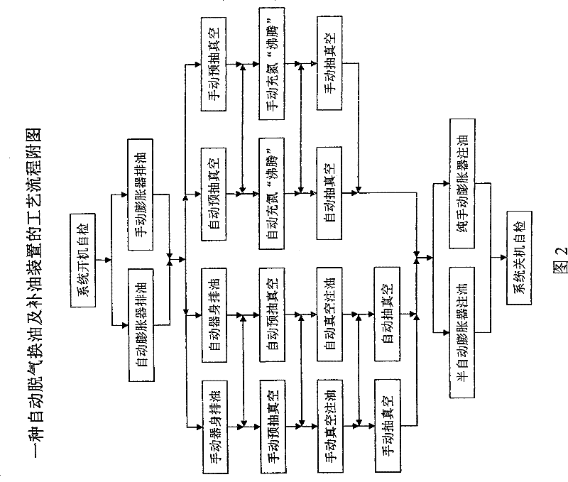

Image

  • Automatic degassing and oil changing device
  • Automatic degassing and oil changing device
  • Automatic degassing and oil changing device

Examples


Embodiment 1

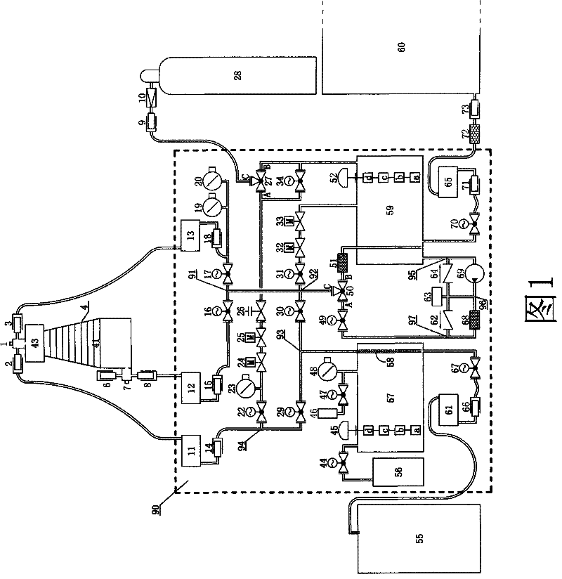
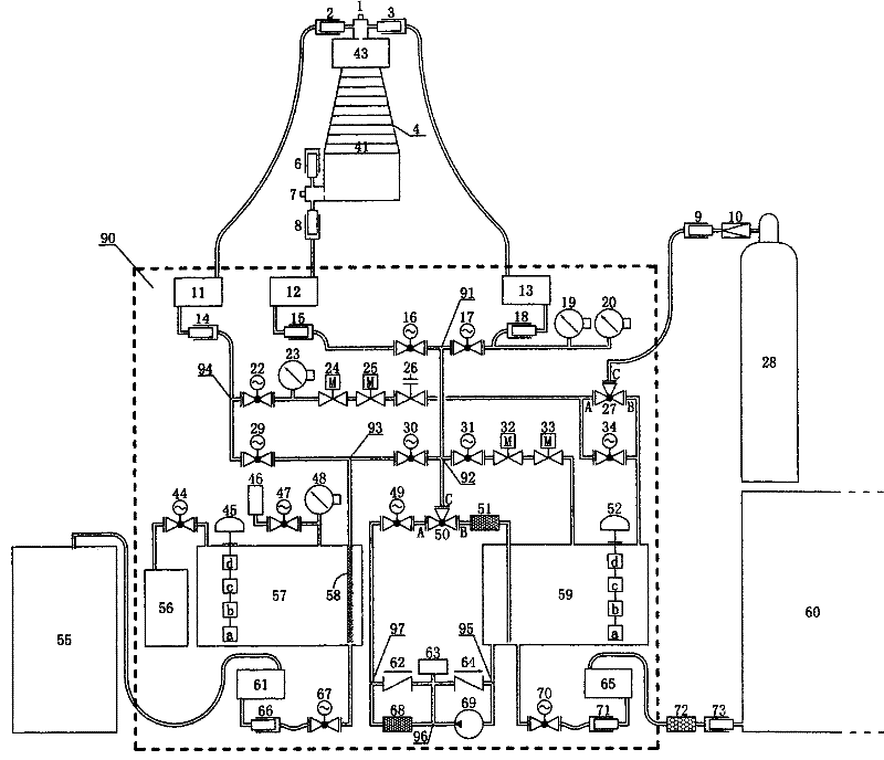
[0016] The invention as shown in Figure 1 is a kind of automatic degassing and oil changing device, comprises nitrogen bottle 28, high pressure transformer 4, automatic degassing and oil changing device 90, waste oil barrel 55, new oil barrel 60, wherein nitrogen bottle 28, The high voltage transformer 4, the waste oil barrel 55 and the new oil barrel 60 are respectively connected with the automatic degassing and oil changing device 90.

[0017] The high-voltage transformer 4 includes a body 41 and an expander 43 positioned on the top of the body 41. The bottom of the body 41 is connected with a vacuum refueling joint 7, and the vacuum refueling joint 7 is connected to the quick connectors 6 and 8 respectively, and the quick connector 8 is connected to the The pipeline in the automatic degassing and oil changing device 90 is connected, and the hose storage device 12, the quick joint 15 and the electric vacuum ball valve 16 are installed in sequence on the pipeline, and then the...


PUM


Abstract

The invention discloses an automatic degassing and oil changing device, which comprises a nitrogen cylinder, a high-voltage transformer, an automatic degassing and oil changing device, a waste oil barThe invention discloses an automatic degassing and oil changing device, which comprises a nitrogen cylinder, a high-voltage transformer, an automatic degassing and oil changing device, a waste oil barrel and a fresh oil barrel, wherein the nitrogen cylinder, the high-voltage transformer, the oil barrel and the fresh oil barrel are connected with the automatic degassing and oil changing device resprel and a fresh oil barrel, wherein the nitrogen cylinder, the high-voltage transformer, the oil barrel and the fresh oil barrel are connected with the automatic degassing and oil changing device respectively. The automatic degassing and oil changing device has the advantages of good integrity, special specificity, mobility, ready operation, safety and reliability.ectively. The automatic degassing and oil changing device has the advantages of good integrity, special specificity, mobility, ready operation, safety and reliability.

Description

technical field [0001] The invention relates to an automatic degassing and oil changing device. Background technique [0002] At present, due to the increase of oil chromatographic abnormalities in high-voltage oil-immersed bushings and transformers of 110KV and above, it is often necessary to change oil and degas the equipment. This kind of work requires high technology, and the power outage time of equipment is getting higher and higher. , requires equipment with reliable process and short time. However, there is currently no comprehensive device on the market that meets the actual work requirements of the site and meets the technical requirements of the equipment. The degassing device widely used by the staff is a vacuum degassing and oil changing device temporarily assembled on site, which has poor integrity. Vacuum pumps, oil and gas separators, The components such as hoses and electrical controls are completely separated, and the components are stored scattered; the s...

Claims


Application Information

Patent Timeline
Patent Type & Authority Patents(China)
IPC IPC(8): H01F27/14
Inventor 高林倪钱杭周建平叶建明章剑光吕建龙
Owner STATE GRID ZHEJIANG ELECTRIC POWER CO LTD SHAOXING POWER SUPPLY CO
Learn More