Posterior stabilized knee prosthesis

A technology of knee joint prosthesis and main body, applied in the direction of knee joint, prosthesis, elbow joint, etc., can solve the problem of increasing the total mechanical failure of piles

Active Publication Date: 2009-09-02
NEW YORK SOC FOR THE RUPTURED & CRIPPLED MAINTAINING THE HOSPITAL FOR SPECIAL SURGERY
View PDF4 Cites 38 Cited by
  • Summary
  • Abstract
  • Description
  • Claims
  • Application Information

AI Technical Summary

Problems solved by technology

In rare cases, this deformation can increase the total mechanical failure of the pile

Method used


Image

  • Posterior stabilized knee prosthesis
  • Posterior stabilized knee prosthesis
  • Posterior stabilized knee prosthesis

Examples


Embodiment approach

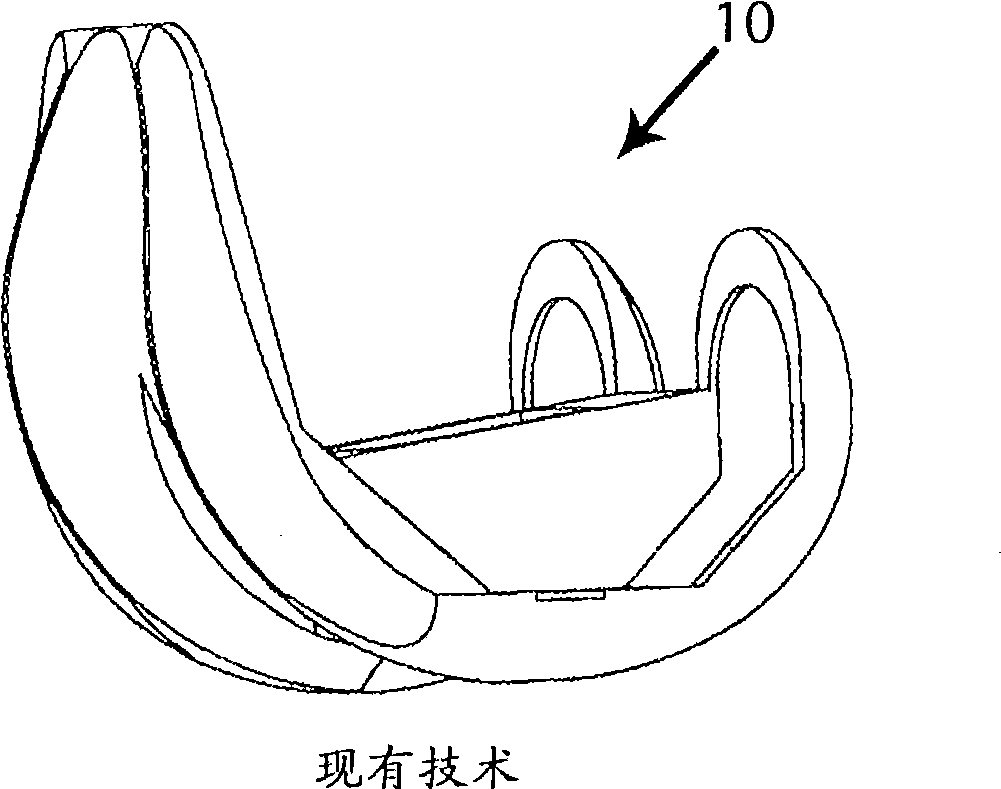
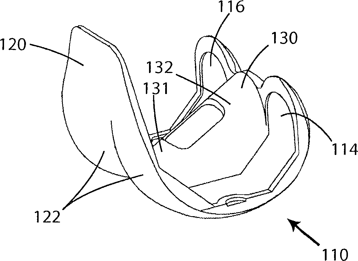
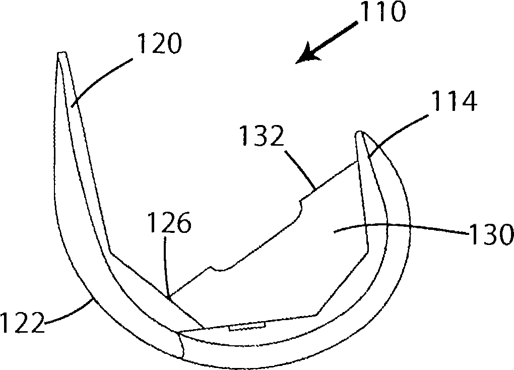
[0038] According to an exemplary embodiment, modification of the geometry of the cassette according to the invention resulted in an average reduction of the volume of bone removed from the intercondylar portion of the femur by approximately 37%. The reduction in bone removal was accomplished by two measures. First, if Figure 6 As shown, the angle of the intercondylar portion 130 of the femoral component 110 is increased to minimize the anteriorly removed bone. For example, the angle of the box measured from the highest point of the top 132 is significantly increased relative to the angle of the box of the traditional intercondylar portion, and at Figure 2-6 In the embodiment shown, the angle of the cassette is increased from 8.3° (traditional design) to approximately 28°. However, it should be understood that the above values ​​are non-limiting and merely exemplary in nature, therefore, the angle of the cassette may be from about 20 degrees to about 35 degrees, such as fro...


PUM


Abstract

A knee joint prosthesis includes a femoral component having an anterior side, a posterior side, a pair of laterally spaced condylar portions, and an intercondylar portion joining the condylar portions and including a recess. A cam surface is located adjacent the intercondylar recess on the anterior side of the femoral component and has a saddle shape that is defined by an at least substantially concave first radius of curvature and a convex third radius of curvature that is perpendicular to the concave first radius of curvature. The prosthesis also includes a tibial component including a platform having an upper surface that includes first and second laterally spaced concavities. Each concavity is adapted for receiving one condylar portion of the femoral component. The tibial component has a tibial post for reception in the intercondylar recess of the femoral component. The tibial post has a saddle shaped anterior cam surface that is complementary to the saddle shaped anterior cam surface of the femoral component and is defined by an at least substantially convex second radius of curvature and a concave fourth radius of curvature that is perpendicular to the convex second radius of curvature.

Description

[0001] Cross References to Related Applications [0002] This application claims priority to US Provisional Patent Application Serial No. 60 / 826,844, filed September 25, 2006, which is hereby incorporated by reference in its entirety. technical field [0003] The present invention relates generally to joint replacement surgery, and more particularly to a posterior stabilized knee prosthesis that includes a modified anterior cam surface of the femur and a modified anterior face of the tibial insert stabilization post such that stresses on these surfaces Lowering and less deformation of the anterior face of the post, as well as less bone removal during surgery. Background technique [0004] Joint replacement surgery is common and enables many people to function normally who would otherwise not be able to. Typically, artificial joints include metal, ceramic, and / or plastic components that are fixed to preexisting bone. The knee joint is one of many common joints that undergo ...

Claims


Application Information

Patent Timeline
Patent Type & Authority Applications(China)
IPC IPC(8): A61F2/38
CPCA61F2/3886A61F2/3859A61F2/389A61F2230/0095A61F2002/30301A61F2/3836
Inventor J·利普曼A·拉比诺维克兹
Owner NEW YORK SOC FOR THE RUPTURED & CRIPPLED MAINTAINING THE HOSPITAL FOR SPECIAL SURGERY
Why Eureka
Try Eureka