Extrusion die for metallic material

A metal material, extrusion die technology, applied in the direction of metal extrusion die, etc., can solve the problems of reduced dimensional accuracy of extruded items, difficulty in obtaining high quality, etc.

Inactive Publication Date: 2009-09-02
SHOWA DENKO KK
View PDF5 Cites 2 Cited by
  • Summary
  • Abstract
  • Description
  • Claims
  • Application Information

AI Technical Summary

Problems solved by technology

This prevents the smooth introduction of metal materials, thereby reducing the dimensional accuracy of extruded items, which in turn makes it difficult to obtain high quality

Method used


Image

  • Extrusion die for metallic material
  • Extrusion die for metallic material
  • Extrusion die for metallic material

Examples


no. 1 approach

[0185] Figures 1 to 13 is an explanatory diagram showing an extrusion die for a metallic material according to a first embodiment of the present invention.

[0186] The extrusion die 10 for metallic materials according to the first embodiment is designed to extrude such as Figure 12 and 13 The multi-channel hollow part (multi-channel flat tube) 60 is shown.

[0187] The hollow member 60 is a metal member. In this embodiment, the hollow member 60 constitutes a heat exchange tube made of aluminum or an aluminum alloy.

[0188] The hollow member 60 is a flat member whose width is larger than the thickness and which is used in a heat exchanger (for example, a condenser for an automobile air conditioner). The hollow portion 61 of the hollow member 60 extends along the tube length direction and is divided into a plurality of heat exchange passages 63 by a plurality of partitions 62 arranged in parallel to each other. These channels 63 extend along the length of the tube and a...

example 1

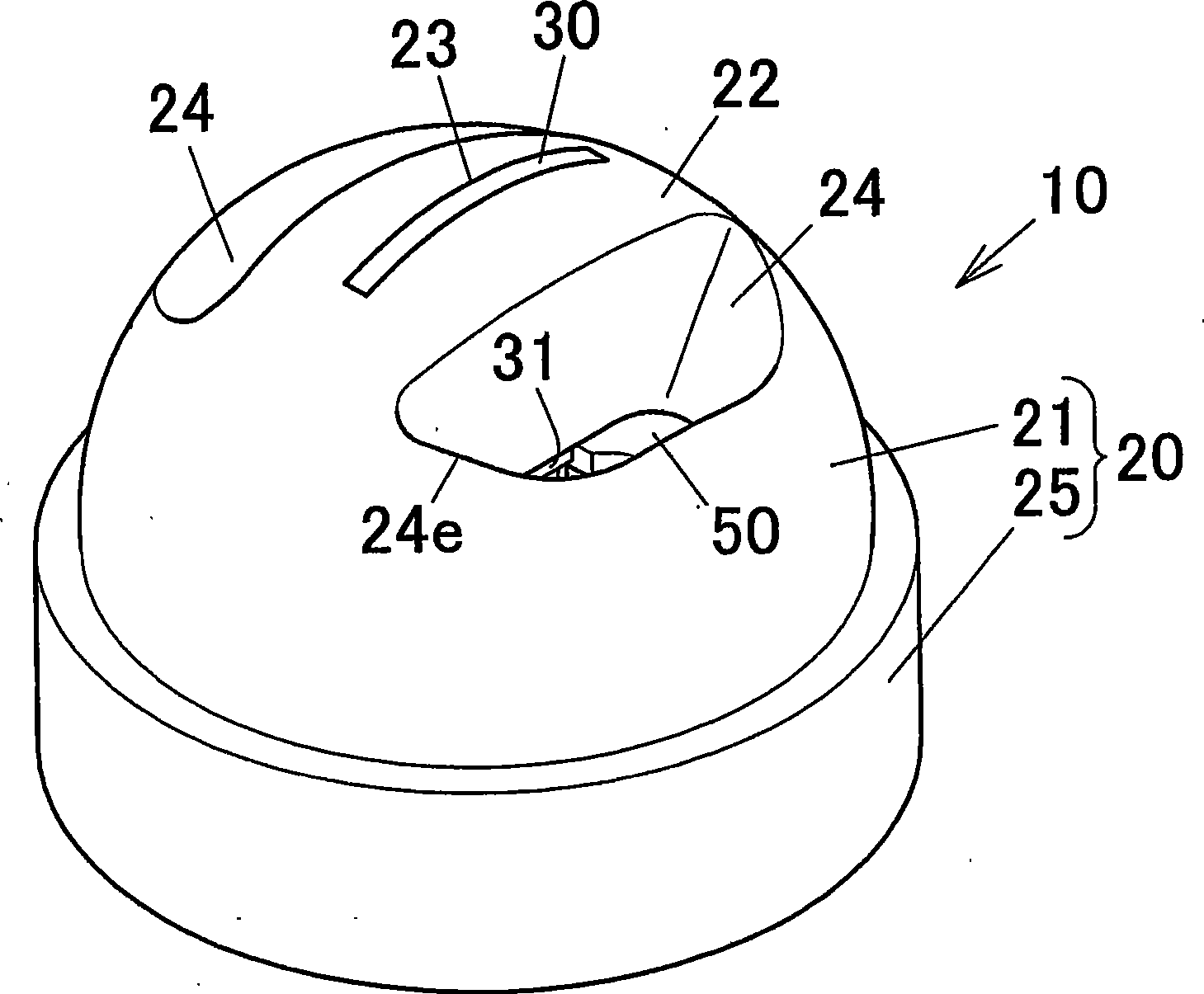
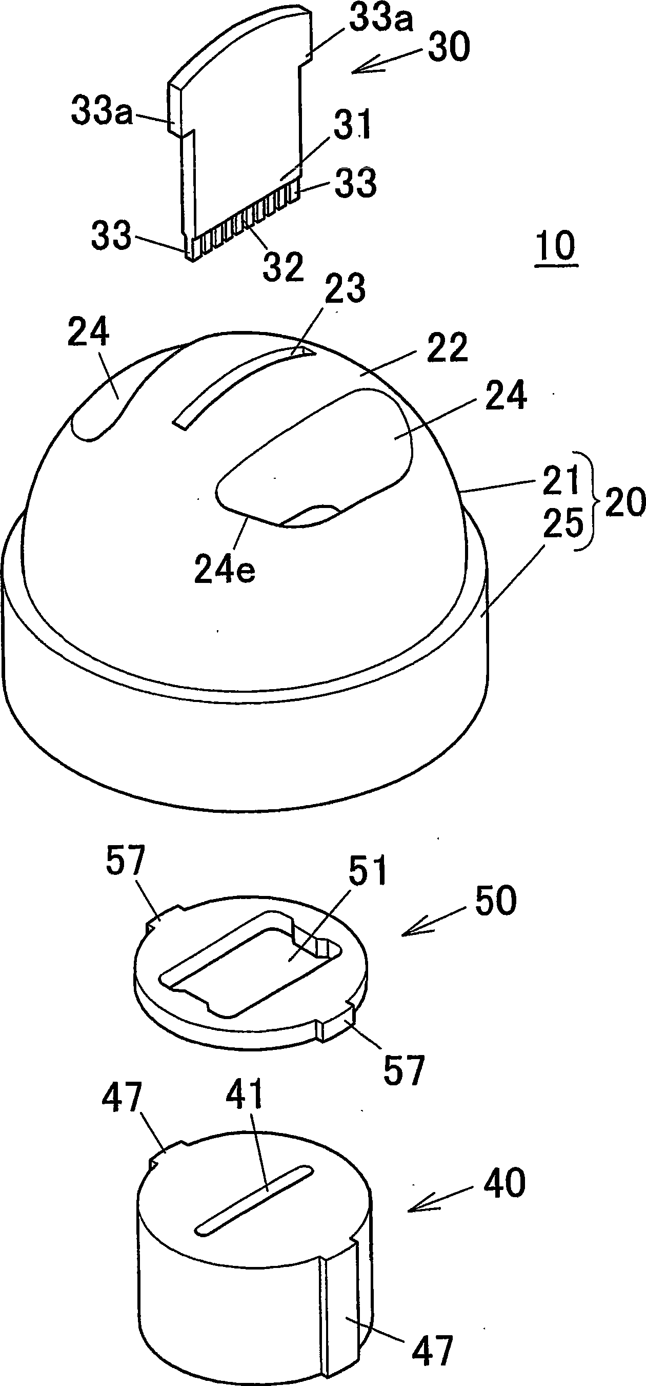
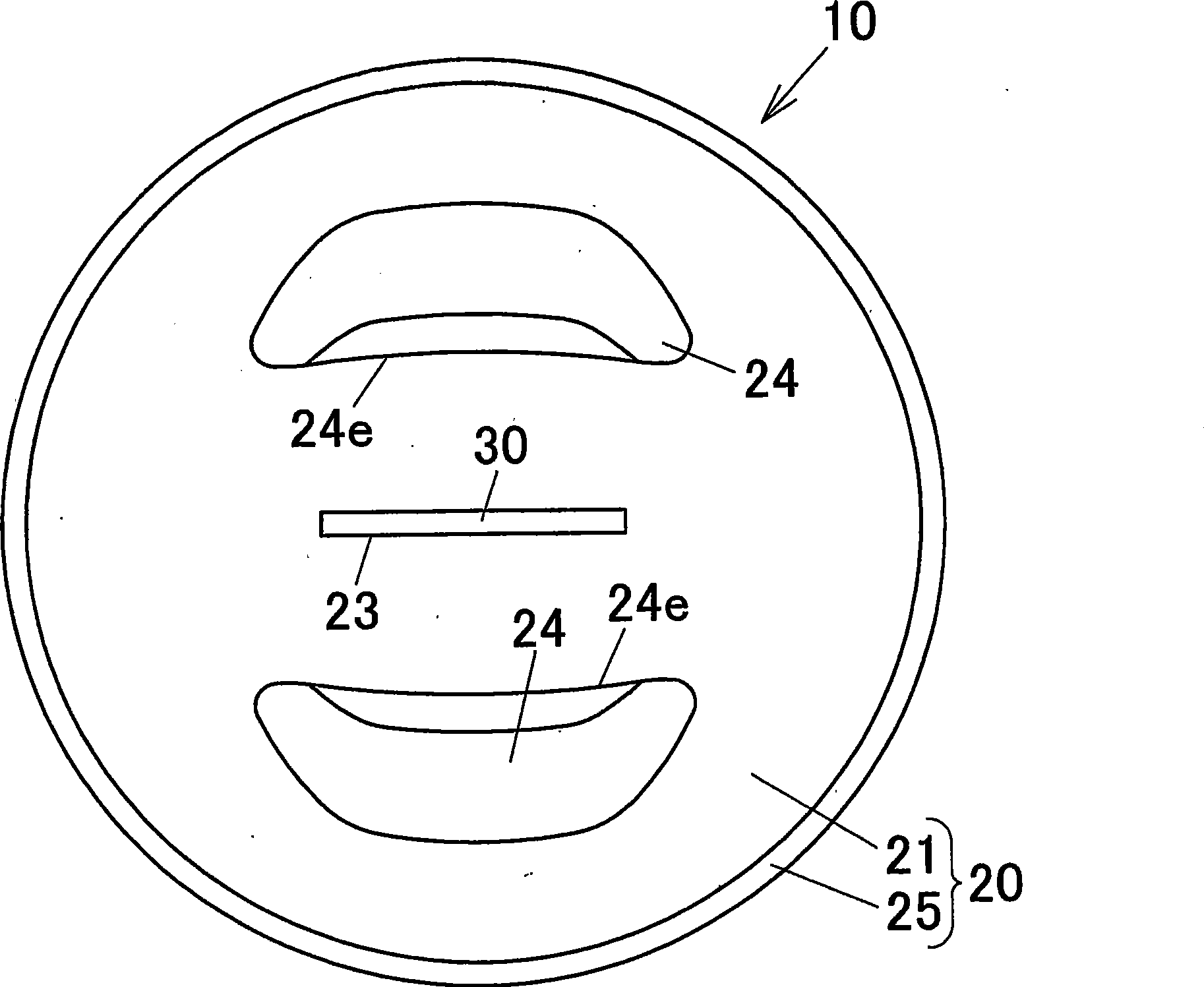
[0251] As shown in Table 1, an extrusion die 10 according to the first embodiment was prepared. The pressure receiving portion 21 of the die case 20 of the die 10 has two channels 24 formed on both thickness direction sides of the extrusion hole 11 . The inclination angle θ of the tunnel 24 is adjusted to be 10°.

[0252] The billet pressure receiving surface 22 was formed in a 1 / 2 spherical configuration (convex spherical configuration) with a radius of 30 mm.

[0253] The ratio (2×Sb / Sa) of the planar state opening total area Sb of the cell inlet portion 24e to the planar state area Sa of the pressure receiving portion 21 was set to 0.1 (area ratio per cell was set to 0.05).

[0254] The male mold 30 is adjusted to: the height (thickness) of the mandrel 31 is 2.0 mm, the width of the mandrel 31 is 19.2 mm, the height of the channel forming protrusion 33 is 1.2 mm, the width of the channel forming protrusion 33 is 0.6 mm and the separation The width of the portion forming g...

example 2

[0260] As shown in Table 1, the ratio (2×Sb / Sa) of the planar state opening total area Sb of the cell inlet portion 24e to the planar state area Sa of the pressure receiving portion 21 is set to 0.15 (the area ratio of each cell is set to 0.075).

[0261] Except for the above, an extrusion die 10 having the same structure was prepared, and extrusion was performed in the same manner as above to be evaluated in the same manner as above.


PUM

PropertyMeasurementUnit
radiusaaaaaaaaaa
radiusaaaaaaaaaa

Abstract

In some preferred embodiments, an extrusion die 10 for a metallic material includes a die case 20 having a pressure receiving portion 21 with a metallic material pressure receiving surface 22 faced rearward against an extrusion direction, a male die 30 disposed in the die case 20, and a female die 40 disposed in the die case 20. The pressure receiving portion 21 is formed into a convex configuration protruded rearward, and a porthole 24 for introducing the metallic material is provided in an outer periphery of the pressure receiving portion 21. A ratio of a flat state opening area Sb of a porthole inlet portion 24e to a flat state area Sa of the pressure receiving portion 21 is set to 0.15 to 0.80. The extrusion die is configured such that the metallic material pressurized against the metallic material pressure receiving surface 22 is introduced into the die case 20 via the porthole 24 and passes through the extrusion hole 11.

Description

[0001] This application claims Japanese Patent Application No.2006-271726 filed on October 3, 2006, Japanese Patent Application No.2006-275031 filed on October 6, 2006, and Japanese Patent Application No. 2006-275031 filed on March 7, 2007. 2007-56953, Japanese Patent Application No. 2007-57124, filed March 7, 2007, and U.S. Provisional Application S.N. 60 / 887,044, filed January 29, 2007, the entire disclosures of which are incorporated herein by reference This is for reference. [0002] Cross References to Related Applications [0003] This application is an application filed pursuant to 35 U.S.C. §111(a), S.N.60 / 887,044 filed January 29, 2007 under 35 U.S.C. §111(b) as required by 35 U.S.C. §119(e)(1) day's rights. technical field [0004] The present invention relates to an extrusion die for metal materials used to extrude (extrude) metal materials and related technologies. Background technique [0005] As extrusion dies for manufacturing metal hollow extruded products...

Claims


Application Information

Patent Timeline
Patent Type & Authority Applications(China)
IPC IPC(8): B21C25/02
Inventor 平本公寿崎浜秀和
Owner SHOWA DENKO KK
Why Eureka
Try Eureka