Shaping condition deciding method, and shaping condition deciding system
A technology for determining forming conditions and methods, which is applied in the field of determining forming conditions and determining systems for forming conditions, and can solve the problems of multiple materials, costs, and a large amount of time
- Summary
- Abstract
- Description
- Claims
- Application Information
AI Technical Summary
Problems solved by technology
Method used
Image
Examples
Embodiment approach 1
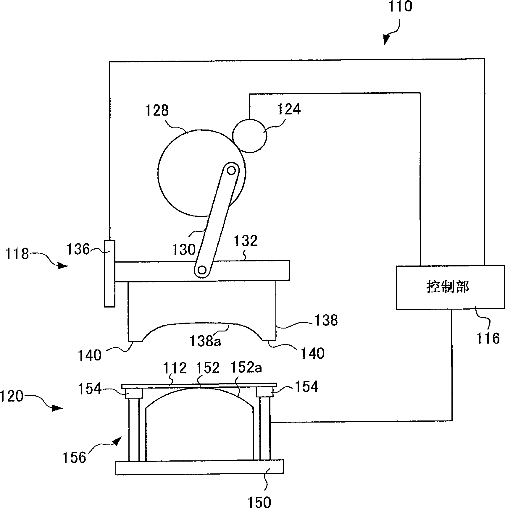
[0089] figure 1 It is a schematic diagram showing the structure of the press machine 110 according to the first embodiment of the present invention.
[0090] The punching machine 110 includes: a lower die mechanism 120 having a lower die 152 disposed on the lower side of the steel plate 112; an upper die mechanism 118 for making the upper die 138 approach or move away from the lower die 152; The control unit 116 that controls the mechanism 118 .
[0091] The upper die mechanism 118 includes: a servo motor 124; a rotary plate 128 rotationally driven by the servo motor 124 via a reduction gear not shown;
[0092] The servo motor 124 is, for example, an AC type that has high responsiveness and small torque deviation. The shaft rotational position of the servo motor 124 is detected by an encoder (not shown), and the servo motor is feedback-controlled based on the detected shaft rotational position.
[0093] The upper die mechanism 118 further includes: a slider 132 pivotally su...
no. 2 approach
[0146] Figure 10 It is a figure which shows the schematic structure of the molding condition determination system 201 which concerns on the 2nd Embodiment of this invention. The molding condition determination system 201 includes an arithmetic processing device 210 connected to a press machine 230 to execute various programs, and an input unit 220 for inputting information into the arithmetic processing device 210 .
[0147] The press machine 230 is a servo press machine driven by a servo, and the forming condition determination system 201 outputs the press forming conditions including forming speed and crease prevention pressure to the press machine 230 .
[0148] The molding condition determination system 201 includes a molding condition optimization unit 211 and a press control data generation unit 214 which are programs deployed on an OS (Operating System Operating System) for operation control.
[0149] The forming condition optimization unit 211 includes a wrinkle prev...
no. 3 approach
[0250] Figure 32 It is a figure which shows the schematic structure of the molding-condition determination system 301 which concerns on the 3rd embodiment of this invention. The forming condition determination system 301 includes a processing device 310 connected to a press machine 330 to execute various programs, and a storage device 320 such as a hard disk for storing information.
[0251] The punching machine 330 is a servo-driven servo punching machine, and the forming condition determination system 301 outputs to the punching machine 330 punching forming conditions including sliding speed and die buffer pressure.
[0252]The molding condition determination system 301 includes a molding condition optimization unit 311 , a molding simulation unit 312 , and a press control data generation unit 313 , which are programs deployed on an OS (Operating System Operating System) for operation control.
[0253] The molding simulation unit 312 performs simulation analysis of molding...
PUM
 Abstract
Description
Claims
Application Information
 - R&D
- Intellectual Property
- Life Sciences
- Materials
- Tech Scout
- Unparalleled Data Quality
- Higher Quality Content
- 60% Fewer Hallucinations
Browse by: Latest US Patents, China's latest patents, Technical Efficacy Thesaurus, Application Domain, Technology Topic, Popular Technical Reports.
© 2025 PatSnap. All rights reserved.Legal|Privacy policy|Modern Slavery Act Transparency Statement|Sitemap|About US| Contact US: help@patsnap.com


