Elevator system

A technology of elevators and braking devices, which is applied in the direction of transportation and packaging, elevators, etc., and can solve the problem of extended stopping distance

Inactive Publication Date: 2009-09-02
MITSUBISHI ELECTRIC CORP
View PDF0 Cites 9 Cited by
  • Summary
  • Abstract
  • Description
  • Claims
  • Application Information

AI Technical Summary

Problems solved by technology

[0004] In the above-mentioned conventional braking device, since the deceleration of the car has been tried to be controlled after the emergency stop command is generated, even...

Method used


Image

  • Elevator system
  • Elevator system
  • Elevator system

Examples


Embodiment approach 1

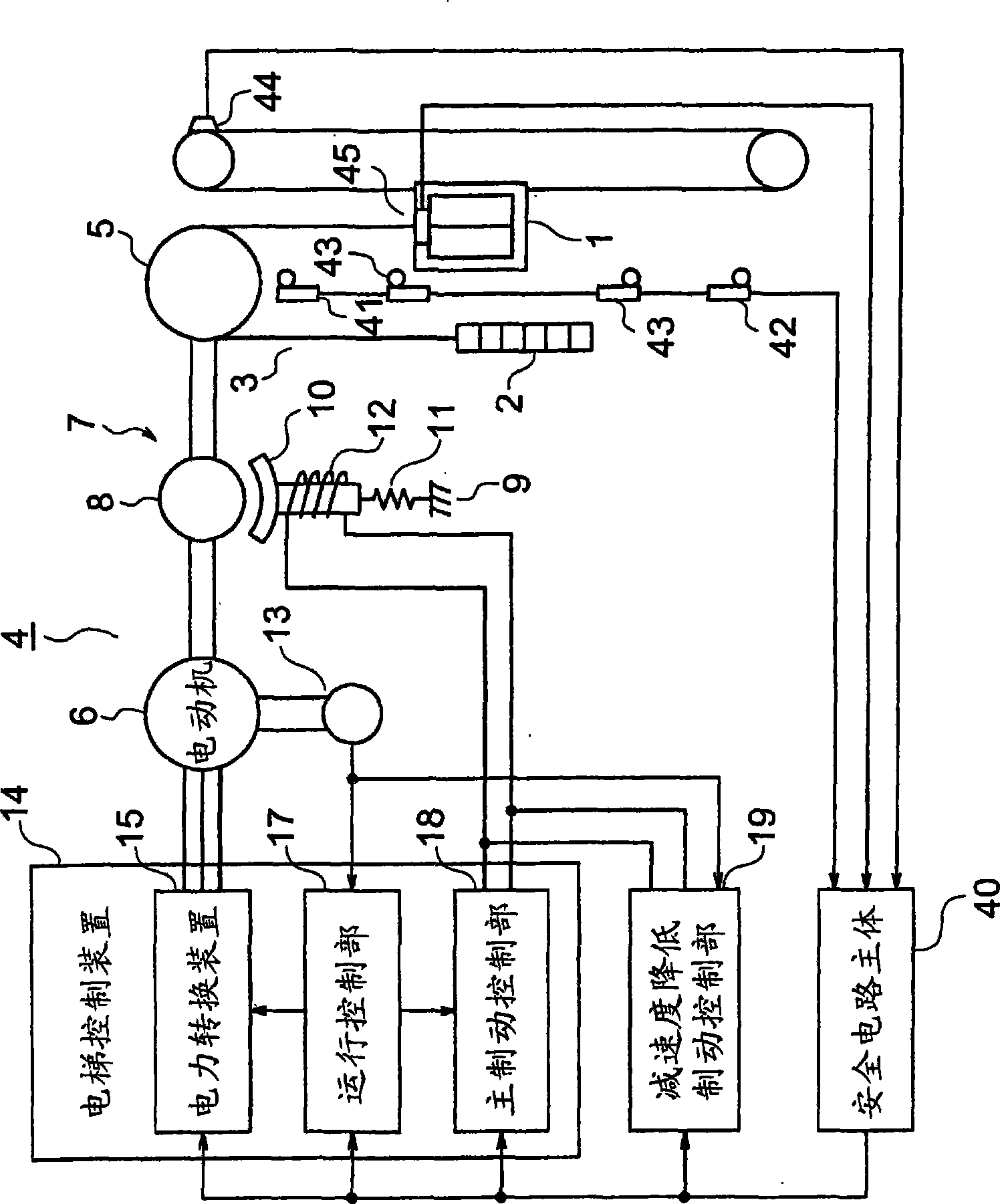
[0015] figure 1 It is a block diagram showing the elevator apparatus of Embodiment 1 of this invention. The car 1 and the counterweight 2 are suspended in the hoistway by the main rope 3, and are raised and lowered in the hoistway by the driving force of the traction machine 4. The hoisting machine 4 has a drive sheave 5 wound with the main rope 3, a motor 6 that rotates the drive sheave 5, and a brake unit 7 that brakes the rotation of the drive sheave 5.

[0016] The brake unit 7 has a brake wheel 8 that rotates together with the drive sheave 5 and a brake device 9 that brakes the rotation of the brake wheel 8. The brake device 9 has a brake shoe 10 that is close to / away from the brake wheel 8, a brake spring 11 that presses the brake shoe 10 on the brake wheel 8, and a brake spring 11 that overcomes the urging force of the brake spring 11. The brake shoe 10 leaves the brake coil 12 of the brake wheel 8.

[0017] The electric motor 6 is provided with a speed detector 13 that g...

Embodiment approach 2

[0045] the following, Figure 4 It is a block diagram showing the elevator apparatus of Embodiment 2 of this invention. In the figure, the elevator control device 14 includes a power conversion device 15, an operation control unit 17 and a brake control unit 20.

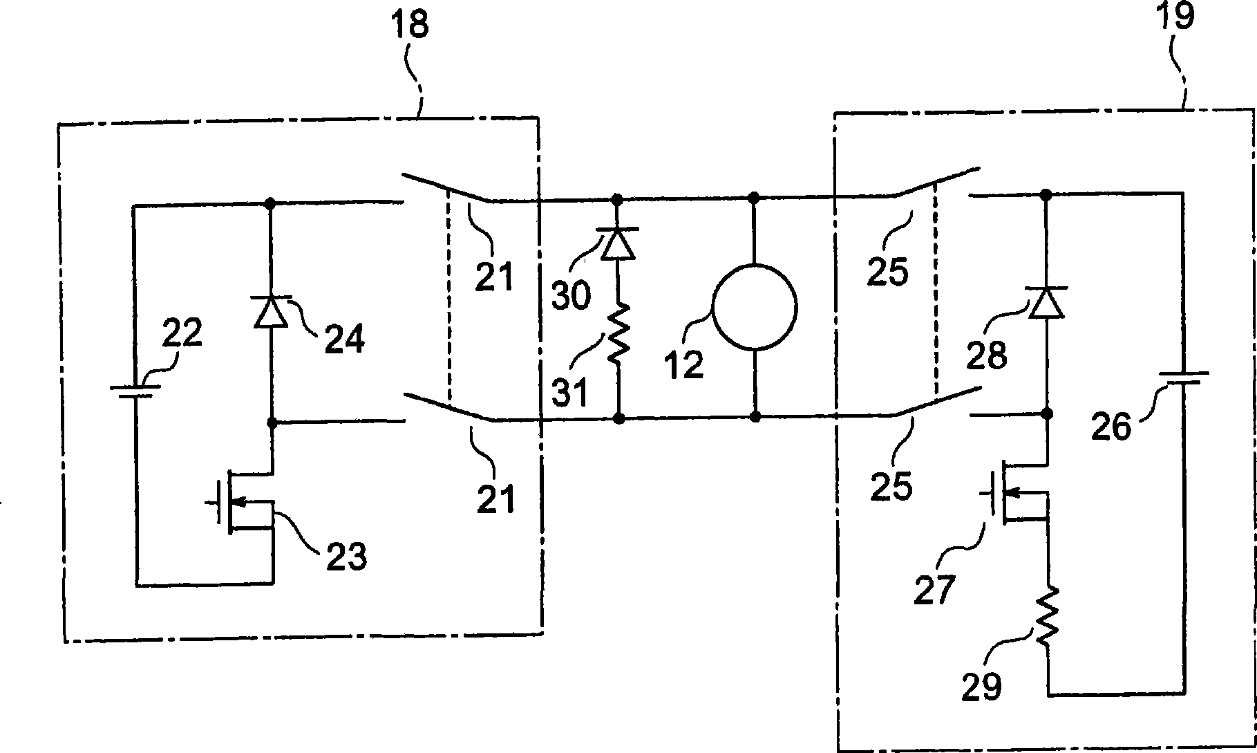
[0046] The brake control unit 20 is used to maintain the stationary state of the car 1 through the braking device 9 when the car 1 is stopped. In addition, the brake control unit 20 causes the brake device 9 to perform a braking operation when an instruction to stop the car 1 urgently is issued. However, at this time, when the deceleration of the car 1 is greater than or equal to the predetermined value, the braking force of the braking device 9 is reduced, and control is performed so that the deceleration of the car 1 is not greater than or equal to the predetermined value. The brake control unit 20 monitors the deceleration of the car 1 based on the information from the operation control unit 17.

[0047] In this way, ...


PUM


Abstract

An elevator system in which a deceleration reducing brake control section reduces deceleration of a cage when it stops suddenly through a brake system by reducing brake force of the brake system. Contact of a safety circuit includes an invalidation contact which is at least one preselected contact, and a validation contact which is at least one contact excluding the invalidation contact. The safety circuit is arranged to invalidate deceleration reducing control by the deceleration reducing brake control section when the invalidation contact is opened, and to validate deceleration reducing control by the deceleration reducing brake control section when the validation contact is opened and the invalidation contact is closed.

Description

Technical field [0001] The present invention relates to an elevator apparatus that reduces the deceleration of a car when the car stops in an emergency. Background technique [0002] In a conventional elevator brake device, during emergency braking, the braking force of the electromagnetic brake is controlled based on the deceleration command value and the speed signal so that the deceleration of the car becomes a predetermined value (for example, refer to Patent Document 1). [0003] Patent Document 1: Japanese Patent Application Publication No. 7-157211 [0004] In the above-mentioned conventional braking device, since an attempt is made to control the deceleration of the car after the emergency stop command is issued, it may be possible to stop the car immediately, for example, when the control unit that controls the deceleration fails. The stopping distance is extended. Summary of the invention [0005] The present invention is proposed to solve the above-mentioned problems,...

Claims


Application Information

Patent Timeline
IPC IPC(8): B66B1/32B66B5/02
CPCB66B1/32B66B5/02B66B5/04
Inventor 柴田益诚
Owner MITSUBISHI ELECTRIC CORP
Why Eureka
Try Eureka