Tappet assembly for a high-pressure pump and high-pressure pump comprising at least one tappet assembly

A high-pressure pump and push rod technology, which is applied to components with teeth, pumps, multi-cylinder pumps, etc., can solve problems such as increasing manufacturing costs, and achieve the effect of avoiding edge support and a simple method.

Inactive Publication Date: 2009-09-02
ROBERT BOSCH GMBH
View PDF1 Cites 19 Cited by
  • Summary
  • Abstract
  • Description
  • Claims
  • Application Information

AI Technical Summary

Problems solved by technology

In order to achieve a precisely parallel extension of the rollers and of the axis of rotation of the drive shaft, in the known high-pressure pumps all components have to be constructed with very small manufacturing tolerances, which correspondingly increases the manufacturing costs

Method used


Image

  • Tappet assembly for a high-pressure pump and high-pressure pump comprising at least one tappet assembly
  • Tappet assembly for a high-pressure pump and high-pressure pump comprising at least one tappet assembly
  • Tappet assembly for a high-pressure pump and high-pressure pump comprising at least one tappet assembly

Examples


Embodiment Construction

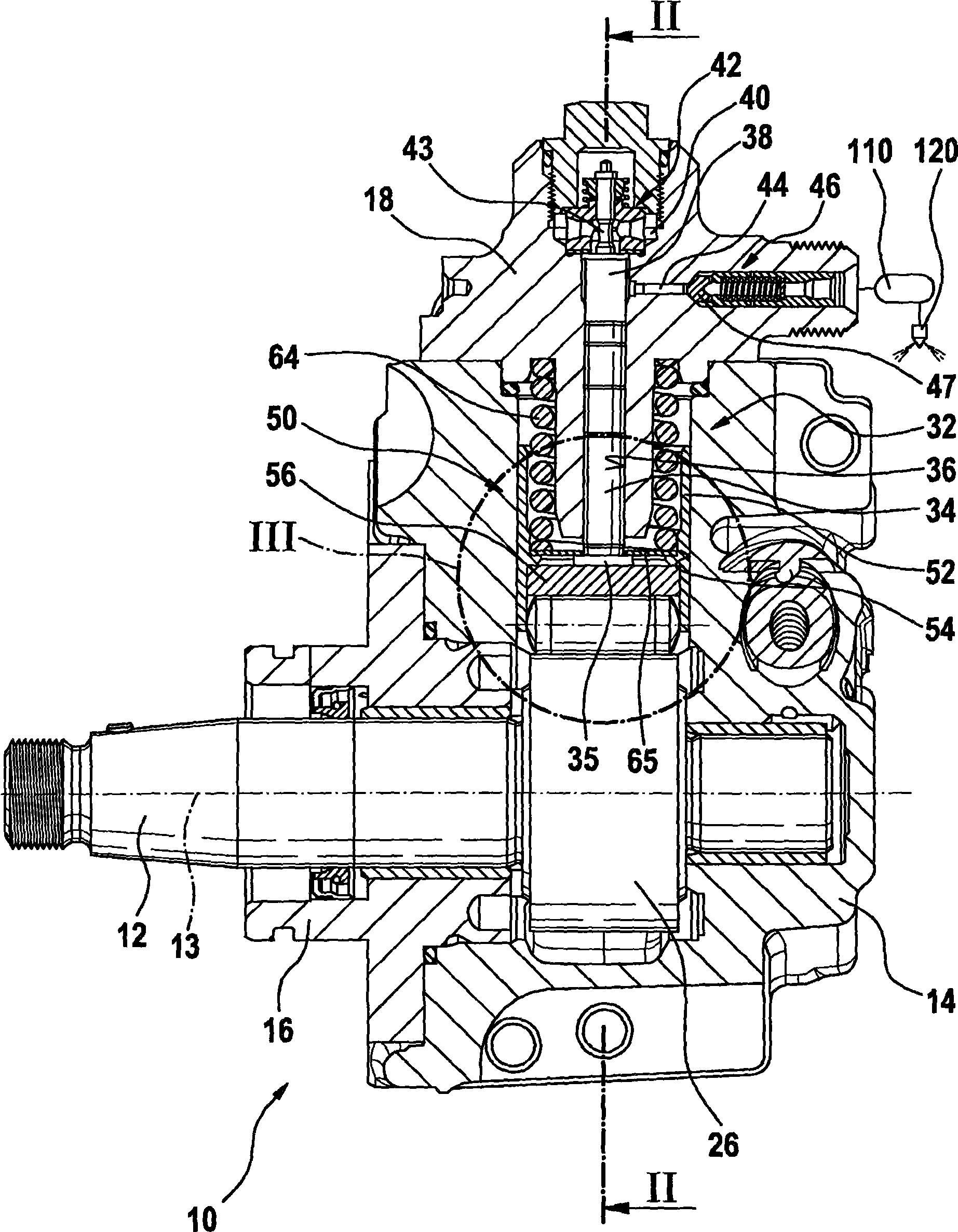
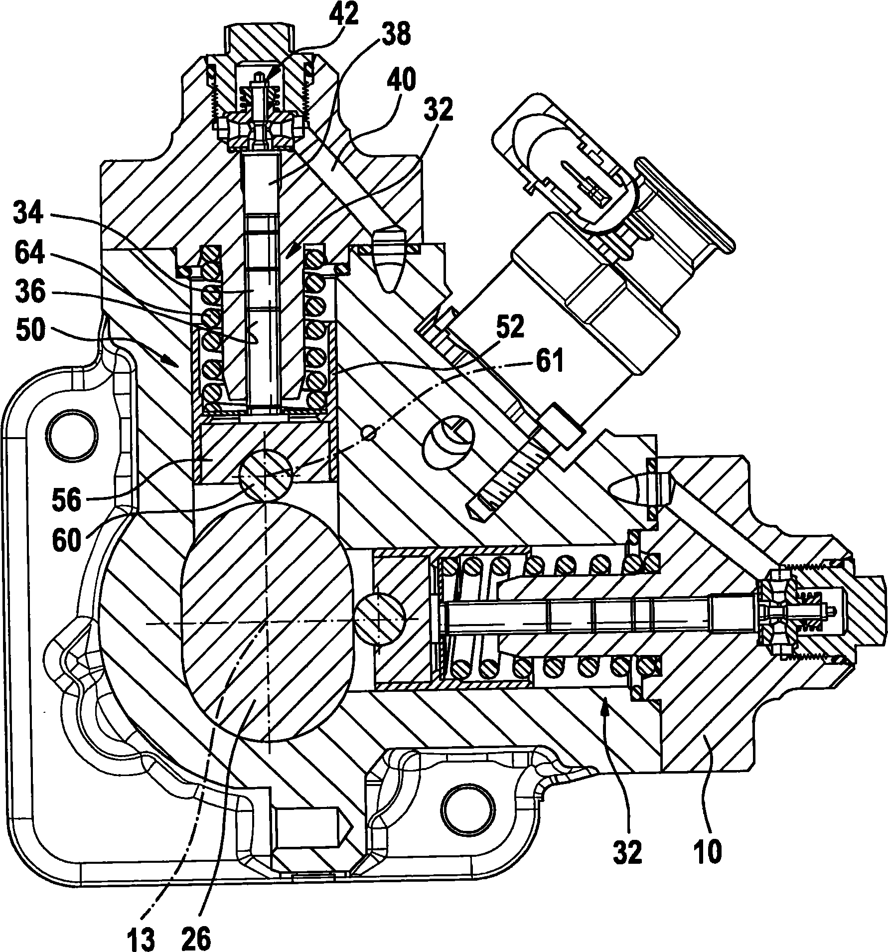
[0014] exist Figures 1 to 8 A high-pressure pump for a fuel injection system for an internal combustion engine is shown in . The high-pressure pump has a multi-part housing 10 in which a rotationally driven drive shaft 12 is arranged. The drive shaft 12 is mounted rotatably in the housing 10 via two bearing points spaced apart from one another in the direction of the axis of rotation 13 of the drive shaft 12 . These bearing points can be provided in different parts 14 , 16 of the housing 10 .

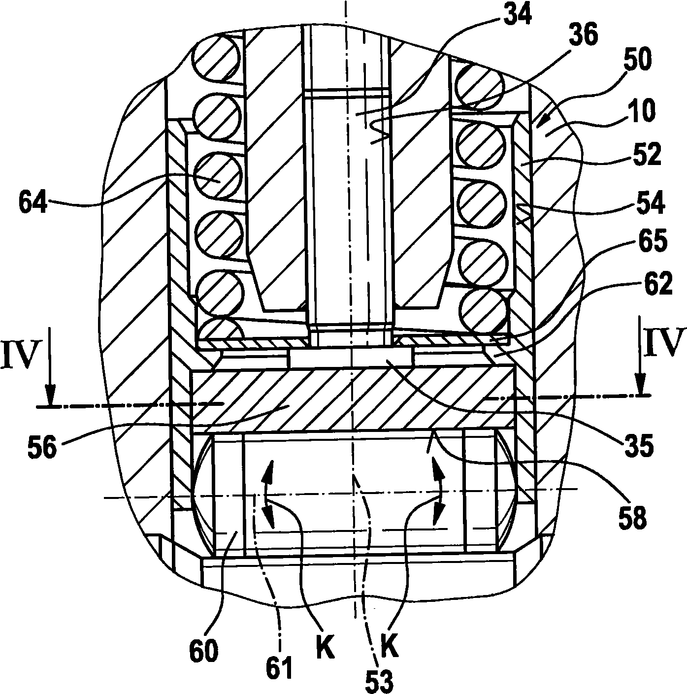
[0015] In the region between these two bearing points, the drive shaft 12 has at least one cam 26 or eccentric, wherein the cam 26 can also be designed as a multi-way cam. The high-pressure pump has at least one or more pump units 32 each arranged in a housing part 18 and each having a pump piston 34 which is indirectly driven via the cam 26 of the drive shaft 12 to drive A reciprocating linear movement is performed in at least approximately radial direction of the axis of rotation ...


PUM


Abstract

The invention relates to a tappet assembly for a high-pressure pump, especially for the purpose of fuel supply, and to a high-pressure pump comprising said tappet assembly. The tappet assembly has a hollow cylindrical tappet base (52) into which a roller support (56) is inserted in the direction of the longitudinal axis (53) of the tappet base (52), a roller (60) being rotatably received in the roller support (56). The roller support (56) is arranged at a right angle to the rotational axis (61) of the roller (60) with little or no play in the tappet base (52) and in the direction of the rotational axis (61) of the roller (60) with larger play than at a right angle to the rotational axis (61) of the roller (60) in the tappet base (52). As a result, the roller support (56) can perform a limited tilting motion in the tappet base (52), thereby allowing the rotational axis (61) of the roller (60) to be aligned in relation to the rotational axis (13) of a driving shaft (12) driving the tappet assembly (50) in a lifting motion and avoiding edge loading of the roller (60) on a cam (26) or avoiding the need for eccentrics on the driving shaft (12).

Description

technical field [0001] The invention relates to a plunger assembly for a high-pressure pump of the type according to claim 1 and a high-pressure pump of the type according to claim 8 or 9 with at least one plunger assembly. Background technique [0002] Such a plunger assembly and a high-pressure pump are known from DE 103 45 061 A1. The high-pressure pump has at least one push rod assembly, which in turn has a hollow cylindrical push rod body and a roller seat inserted into the push rod body along the longitudinal axis of the push rod body, in which roller seat A roller is rotatably supported. The high-pressure pump has at least one pump unit, which in turn has a pump piston, by which a pump working chamber is delimited. The push rod assembly is arranged between the pump piston and a rotationally driven drive shaft of the high-pressure pump, wherein the drive shaft has at least one cam or eccentric on which the roller runs. The plunger body is displaceably guided in a bo...

Claims


Application Information

Patent Timeline
Patent Type & Authority Applications(China)
IPC IPC(8): F02M59/10F04B1/04F16H53/06
CPCF02M59/06F04B1/0439F02M59/102Y10T74/2107
Inventor W·富克斯
Owner ROBERT BOSCH GMBH
Why Eureka
Try Eureka