Wireless diagnostic systems

A diagnostic system, wireless technology, used in diversity/multi-antenna systems, transmission systems, digital transmission systems, etc.

Inactive Publication Date: 2009-09-02
FINISAR
View PDF0 Cites 4 Cited by
  • Summary
  • Abstract
  • Description
  • Claims
  • Application Information

AI Technical Summary

Problems solved by technology

In addition, due to the large size of the diagnostic equipment, it has been difficult to tightly apply the diagnostic equipment to network devices such as storage devices, servers, clients, printers, etc.

Method used


Image

  • Wireless diagnostic systems
  • Wireless diagnostic systems
  • Wireless diagnostic systems

Examples


Embodiment Construction

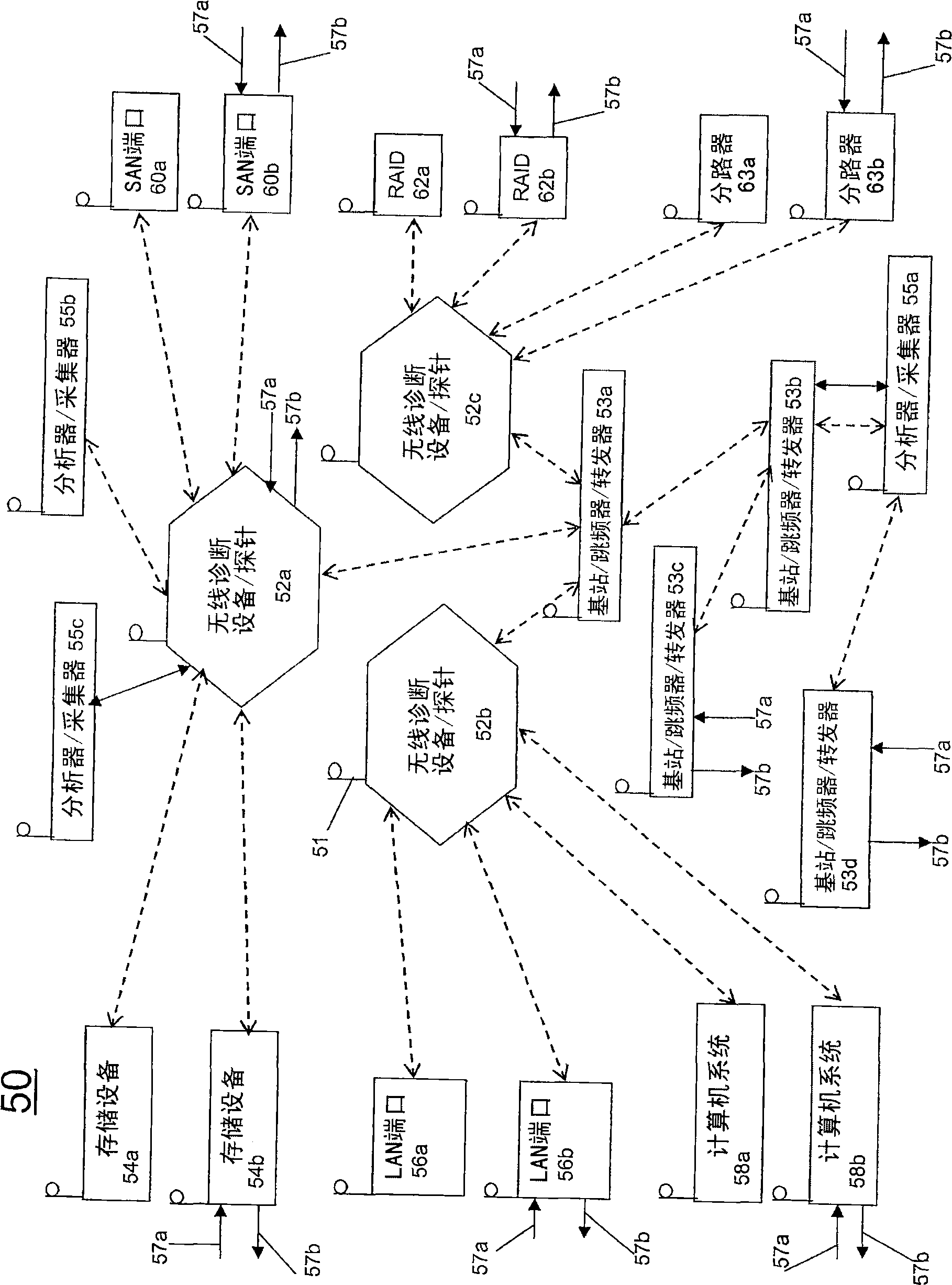
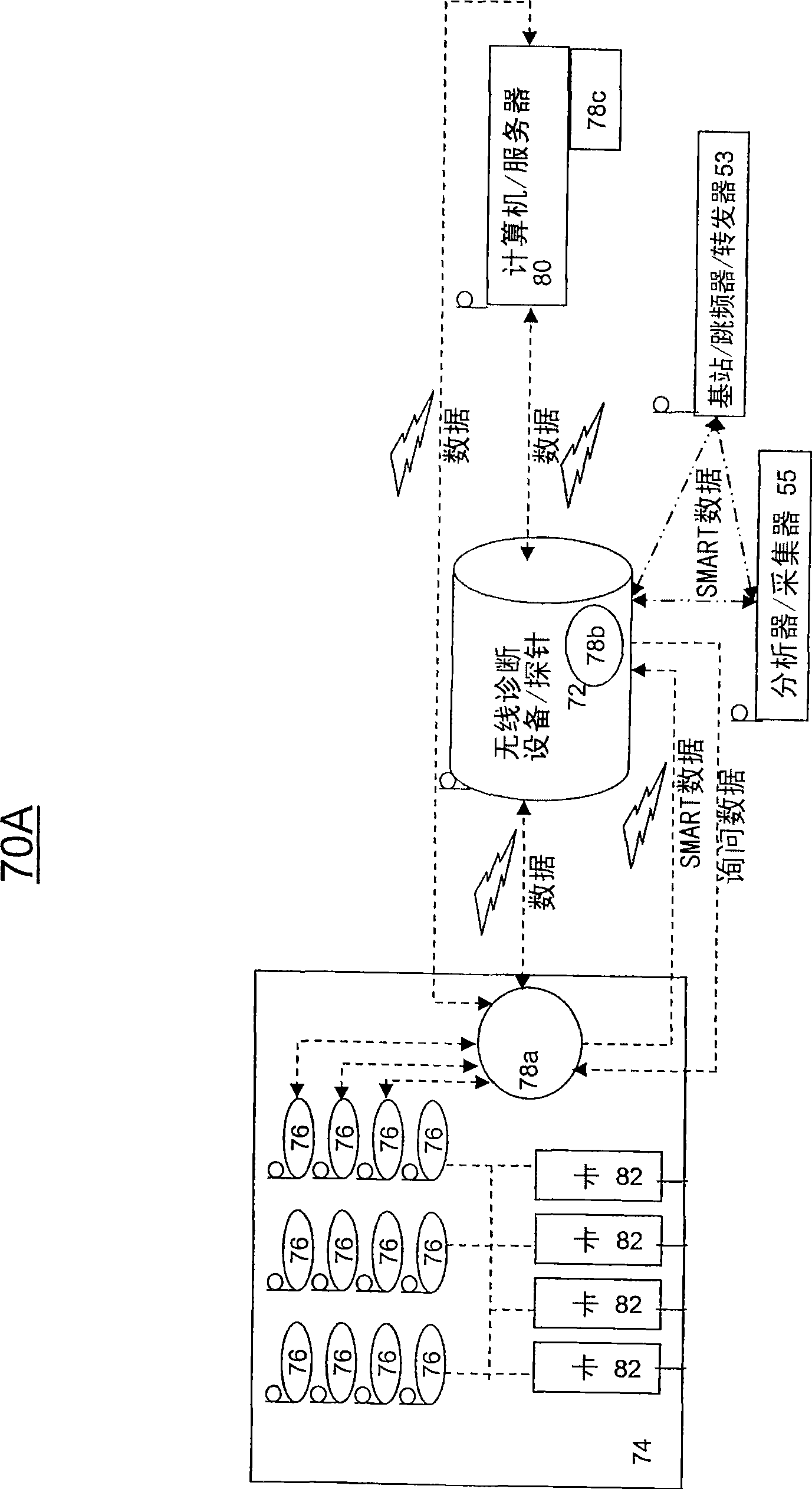
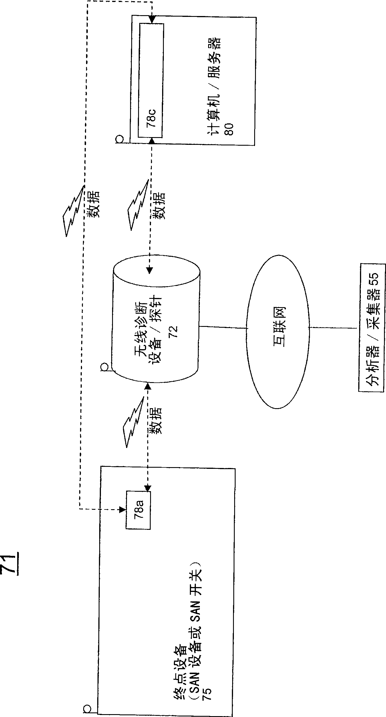
[0026] In general, exemplary embodiments of the present invention relate to diagnostic systems configured to test and / or evaluate components and the like in the diagnostic system. The diagnostic system also involves wireless components for providing additional features and advantages not found in hitherto existing diagnostic systems. Typically, the diagnostic system of the present invention enables high speed transmission. However, embodiments of the present invention may be used in other applications that do not involve detecting system components and / or do not involve high speed data transmission.

[0027] I. Definition

[0028] Where different terms are used consistently and / or interchangeably in the specification and claims, the definitions of these terms are as follows:

[0029] The term "wireless" is used to refer to any data transmission technology that does not occur through a physical transmission medium. The term "physical transmission medium" refers to physical...


PUM


Abstract

The invention discloses wireless diagnostic systems and methods of implementing wireless diagnostic analysis between at least one end point device and at least one wireless diagnostic device / probe, each including a wireless transceiver that enables wireless communication therebetween. The wireless diagnostic device could be a bit error rate tester, a protocol analyzer, a generator, a jammer, a monitor, and the like. The end point devices can be storage devices, LAN ports, computer systems, SAN ports, wireless RAIDS, network taps, and the like.

Description

technical field [0001] The present invention relates to wireless diagnostic systems. More specifically, the present invention relates to remote monitoring of end point devices using wireless communications. Background technique [0002] Diagnostic facilities can be used to obtain information about the operation of different components on the network. A storage area network probe ("SAN probe") is a type of diagnostic device that is configured to monitor and / or analyze components in a SAN. A typical SAN probe is physically connected into the SAN by using various cables and transceiver modules that establish communication between the probe and the network. While SAN probes are already available to provide accurate real-time statistics, the probes are expensive to install. [0003] Additionally, local area network probes ("LAN probes") are diagnostic devices that can be used to monitor and / or analyze a LAN. LAN probes have been used to monitor, measure, analyze and troublesh...

Claims


Application Information

Patent Timeline
Patent Type & Authority Applications(China)
IPC IPC(8): H04B17/00H04B7/02H04L1/00H04L12/26
CPCH04K2203/18H04B7/022H04K3/46H04B17/0085H04K3/45H04K3/94H04K2203/36H04B17/00H04B17/10H04B17/20
Inventor 盖儿·萝瑞塔·诺伯德瑞克·安东尼·琼斯强纳森·麦可·韩德森威廉·大卫·提柏
Owner FINISAR
Why Eureka
Try Eureka