Radio base station, relay station, and communication control method
A technology for wireless base stations and relay stations, applied in the fields of relay stations, communication control, and wireless base stations, can solve the problems of incomplete uplink burst allocation, and achieve the effect of improving utilization efficiency
- Summary
- Abstract
- Description
- Claims
- Application Information
AI Technical Summary
Problems solved by technology
Method used
Image

Examples
no. 1 example
[0070] First, the first embodiment will be described.
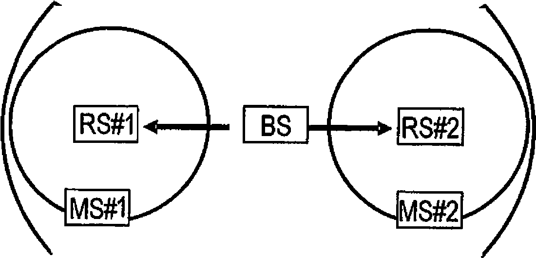
[0071] The first embodiment is an example for appropriately allocating wireless resources at the time of wireless communication between the wireless base station BS and the wireless terminal MS via the relay station RS.
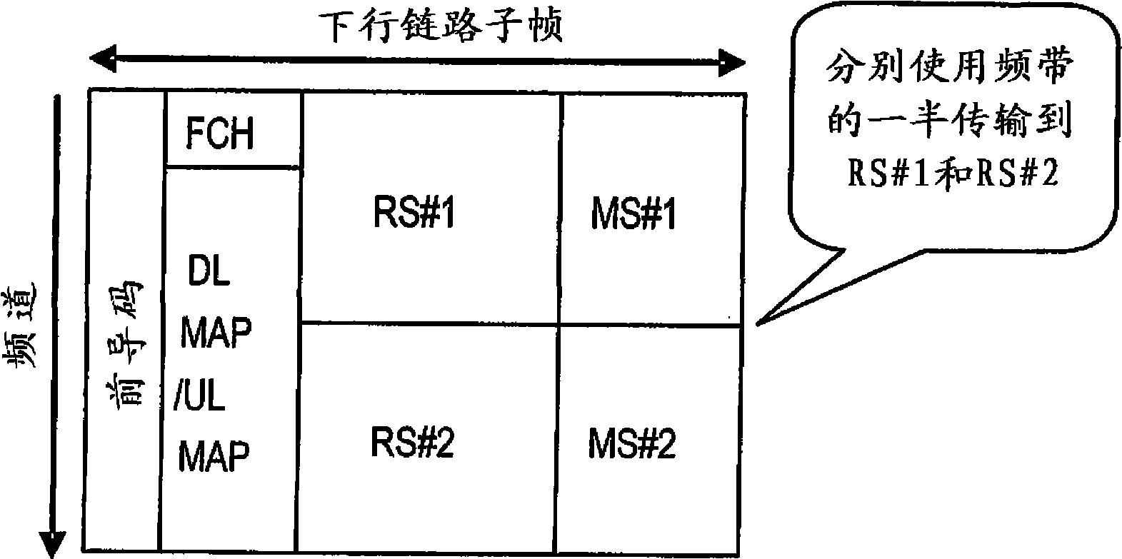
[0072] Figure 1A An example of a subframe in the downlink direction is described (the abscissa is time (transmission timing), and the ordinate is channel).
[0073] Such as Figure 1A As shown, radio resources are allocated to relay stations RS#1 and RS#2 so as to utilize half of the frequency band for simultaneous transmission. Wireless resources are also allocated to wireless terminals MS#1 and MS#2 so as to utilize half of the frequency band for simultaneous transmission. For the allocation, the DL-MAP messages are set such that the transmission regions (channel and time) do not overlap between bursts.
[0074] By allocating radio resources in this way, data is simultaneously transmitted from the...
no. 2 example
[0077] A second embodiment will now be described.
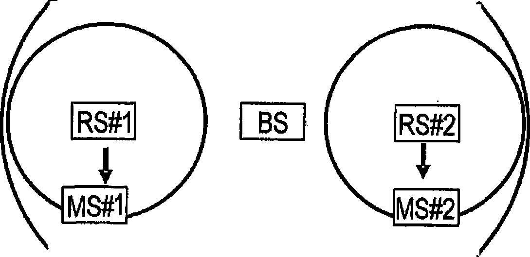
[0078] In the first embodiment, radio resources are allocated to the relay station RS and the subordinate radio terminal MS so that the corresponding transmission areas (frequency channels, transmission timing) do not overlap. However, even if there are a plurality of relay stations RS under the radio base station BS and the respective relay stations RS are deployed at positions where mutual interference does not occur (for example, such that the coverage areas of the respective relay stations (areas that provide radio communication services to radio terminals) do not overlap) different wireless resources are also allocated respectively.
[0079] Therefore, according to the second embodiment, the radio base station BS manages the relay stations RS that do not interfere with each other, and just allocates downlink bursts (radio resource allocation in the downlink direction) to the radio terminals MS under such relay stations R...
no. 3 example
[0131] A third embodiment will now be described.
[0132] In this embodiment, consider the following example. Figure 8 An example of distribution of wireless terminals MS is described. Such as Figure 8 As shown, the wireless terminals MS#1, MS#2 and MS#3 are located at the cell edge of the relay station RS. Assume that relay stations RS#1 and RS#2 and these wireless terminals MS#1, MS#2 and MS#3 communicate according to QPSK. It is also assumed that the wireless terminal MS#4 located near the relay station RS#2 communicates according to 16QAM, whereby fast communication is possible. It is assumed that each relay station RS transmits the same amount of data to each wireless terminal MS. In this case, the data destined for the wireless terminal MS#4 can be transmitted using wireless resources that are half the wireless resources (the number of subchannels) of the other wireless terminal MS. The relay stations RS#1 and RS#2 do not interfere with each other.
[0133] Fig...
PUM
 Abstract
Description
Claims
Application Information
 - R&D
- Intellectual Property
- Life Sciences
- Materials
- Tech Scout
- Unparalleled Data Quality
- Higher Quality Content
- 60% Fewer Hallucinations
Browse by: Latest US Patents, China's latest patents, Technical Efficacy Thesaurus, Application Domain, Technology Topic, Popular Technical Reports.
© 2025 PatSnap. All rights reserved.Legal|Privacy policy|Modern Slavery Act Transparency Statement|Sitemap|About US| Contact US: help@patsnap.com