Wireless base station, relay station and frequency band allocation method

A wireless base station and frequency band allocation technology, applied in radio relay systems, wireless communications, radio transmission systems, etc., can solve the problem of communication rate reduction and achieve high-speed allocation

Inactive Publication Date: 2009-09-02
FUJITSU LTD
View PDF0 Cites 2 Cited by
  • Summary
  • Abstract
  • Description
  • Claims
  • Application Information

AI Technical Summary

Problems solved by technology

[0004] In this way, IEEE 802.16d and the like are based on P-MP connection, so the service area is limited to the coverage area (cell) covered by the wireless base station 100, and the communication rate decreases at the edge of the cell

Method used


Image

  • Wireless base station, relay station and frequency band allocation method
  • Wireless base station, relay station and frequency band allocation method
  • Wireless base station, relay station and frequency band allocation method

Examples


no. 1 example

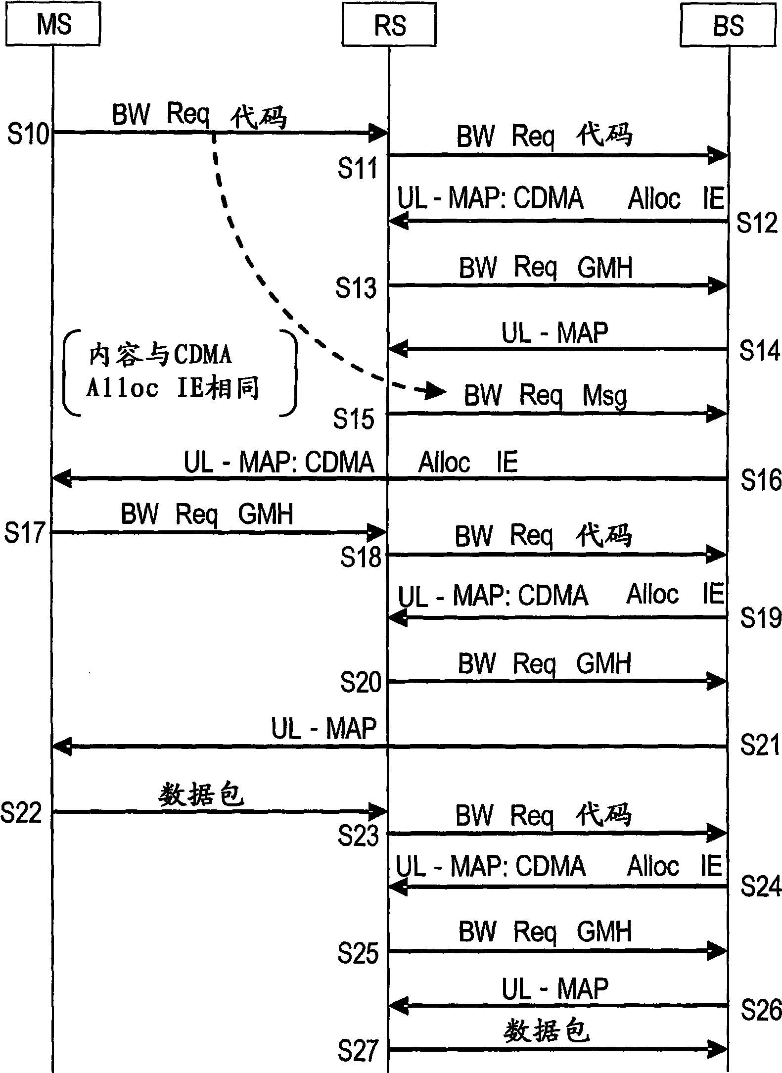
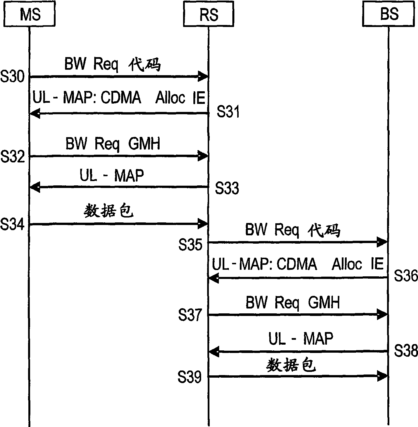
[0050] figure 1 and figure 2 is a diagram illustrating a sequence example of frequency band allocation according to the first embodiment. figure 1 is an example (centralized scheduling) when the radio base station BS generates a UL-MAP message for assigning a transmission band to the radio terminal MS under the relay station RS, and figure 2 is an example when the relay station RS generates the UL-MAP message (distributed scheduling). The wireless communication system has a wireless terminal MS, a relay station, and a wireless base station BS.

[0051] will first describe figure 1 . The radio terminal MS transmits one CDMA code included in the BW Req code (signal sequence) group representing the band request among the CDMA code (signal sequence) groups to the relay station RS (S10). The BW Req code group can be created by a CDMA code.

[0052] The relay station RS that has received the CDMA code notifies the radio base station of information such as the value of the...

no. 2 example

[0077] will now refer to Figure 3 to Figure 9 A second embodiment is described.

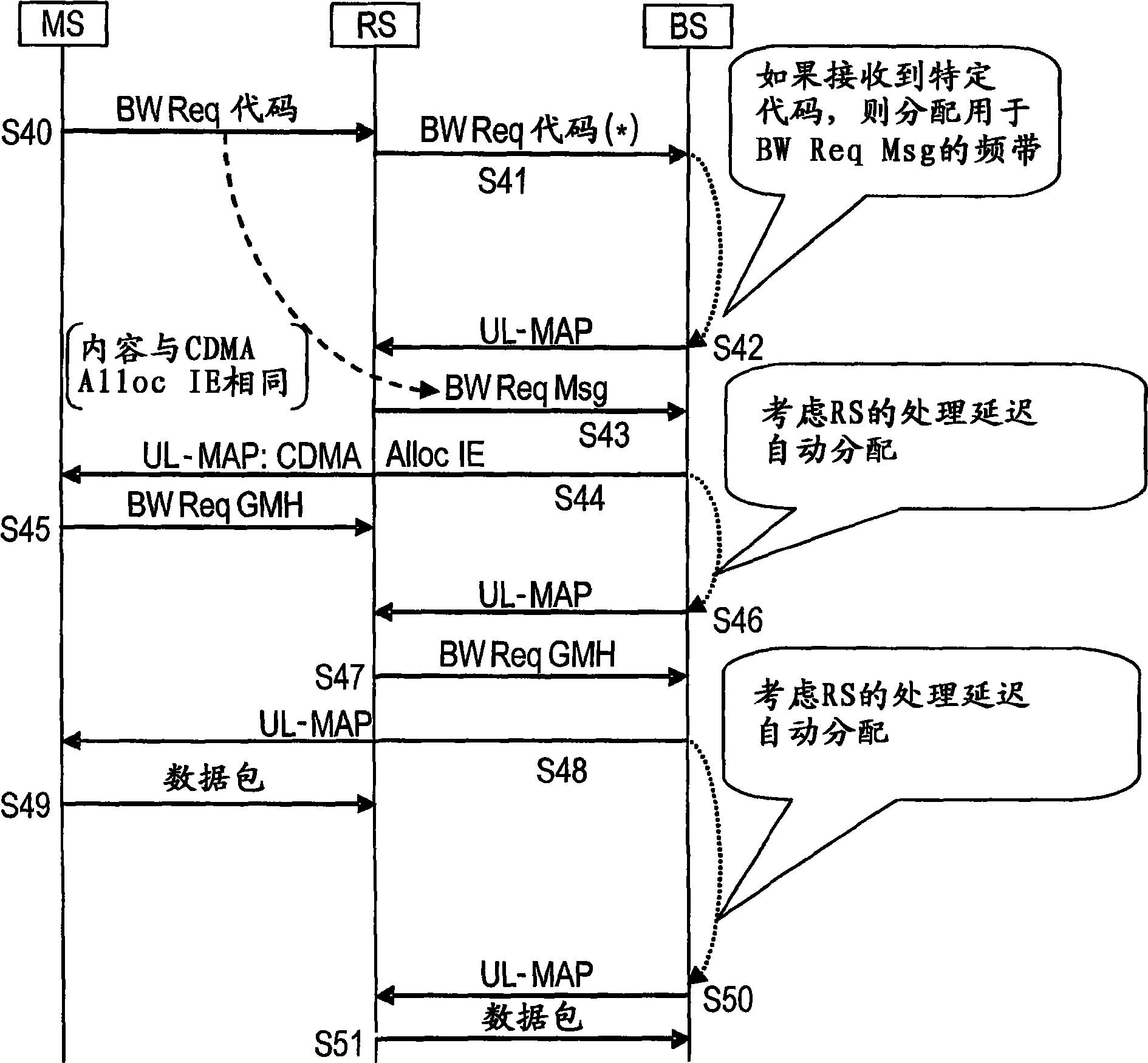
[0078] The second embodiment is an example when the processing speed is higher than that of the first embodiment. In a second embodiment, a relay station RS that receives from a wireless terminal MS one of the CDMA codes (signal sequences) included in a predetermined set of CDMA codes (signal sequences) for bandwidth requests (for example, codes 1, 2, 3) will use the bandwidth The requested predetermined specific CDMA code (for example, code 4) is sent to the radio base station BS.

[0079] In other words, the relay station uses a code different from the CDMA code used for the bandwidth request by the wireless terminal MS as the specific code for the bandwidth request.

[0080] The radio base station BS receiving the specific code recognizes that the bandwidth request is not from the radio terminal MS but from a specific relay station RS, and allocates a required transmission band (predetermin...

no. 3 example

[0137] A third embodiment will now be described.

[0138] In the second embodiment, an example is described in which the relay station RS transmits a BW Req code indicated by a specific code among CDMA codes for requesting a frequency band. The BW Req code represented by the specific code is assigned independently to each relay station RS (see Figure 4A ).

[0139] In the third embodiment, the same specific code is assigned to a plurality of relay stations RS. A common CID (connection ID, referred to as a multicast polling CID in the third embodiment) is assigned to relay stations RS assigned the same specific code.

[0140] For example in image 3 In , the relay station RS transmits the BW Req code indicated by the specific code (S41), but here, the specific code commonly assigned to each relay station RS is transmitted. The radio base station BS that has received the code recognizes that this is a band request from the relay station RS, and generates a UL-MAP message in...


PUM


Abstract

A relay station for relaying communication between a radio base station which allocates to a terminal an uplink channel for notifying a requested band when any signal sequence out of a predetermined signal sequence group is received from the terminal, and allocates a transmission band according to the requested band notified from the terminal via the channel, and the terminal, including: a transmission unit which sends a specific signal sequence not included in the predetermined signal sequence group, wherein the relation station is allocated a predetermined transmission band by the radio base station, without the relation station is not allocated the uplink channel for notifying the requested band by the radio base station which is received the specific signal sequence.

Description

technical field [0001] The present invention relates to a wireless base station, a relay station, and a frequency band allocation method using wireless communication, and particularly to a wireless base station for appropriately allocating a frequency band between a wireless terminal and a wireless base station via a relay station, and the like. Background technique [0002] In IEEE 802.16WG known as an example of wireless communication system standards, two types of wireless communication systems are prescribed: IEEE 802.16d relates to fixed communication (for example, see Non-Patent Document 1 below), and IEEE 802.16e relates to mobile communication ( See, for example, Non-Patent Document 2) below. [0003] Figure 20 An image illustrating services provided according to IEEE 802.16d and IEEE 802.16e. These services are based on a P-MP (Point-to-Multipoint) connection in which a plurality of terminals 101 to 103 are connected to one wireless base station 100 . [0004] In...

Claims


Application Information

Patent Timeline
IPC IPC(8): H04W16/26H04W72/04H04W76/02H04W88/04H04W88/08
CPCH04W84/047H04B7/155H04W88/08G01S5/0018H04W72/0413H04W88/02H04W72/0453H04W72/23H04B7/14H04W72/04
Inventor 奥田将人
Owner FUJITSU LTD
Why Eureka
Try Eureka