
System and method for energy-saving control of compressor unit

A technology of air compressor unit and central control system, which is applied in the field of frequency conversion system, which can solve the problems of complex gas consumption state, rapid pressure drop, and inability to guarantee the effect of constant pressure, so as to achieve the effect of realizing energy and preventing the danger of pressure loss

Inactive Publication Date: 2009-09-09
BEIJING FENGDY S&T
View PDF0 Cites 22 Cited by
  • Summary
  • Abstract
  • Description
  • Claims
  • Application Information

AI Technical Summary

Problems solved by technology

[0004] However, the above method still has many problems in practical application. For example, for normal motor variable frequency drive, the lowest frequency can only reach about 28Hz, and the lowest frequency in winter is only about 20Hz. In other words, the range of fluctuations in many cases is far beyond the range of this value
Then for the compressed air demand value lower than 1 / 4, the adjusted minimum speed cannot guarantee the effect of constant pressure. To ensure that the pressure does not rise, the only option is to stop the machine.
However, if the equipment is shut down and restarted, it will take a certain unloading time. During this time, the pressure will inevitably drop rapidly, and the pressure should be as low as possible.
As for the gas consumption of a factory, it consists of multiple air compressor units. For a complex gas consumption system, the gas consumption status in each time period is very complicated. The adjustment of PID alone can only be used for one kind of work. It is not optimal for other working conditions, and it is even more impossible to guarantee the influence of pressure fluctuations for multi-unit operating conditions.

Method used


Image

  • System and method for energy-saving control of compressor unit
  • System and method for energy-saving control of compressor unit
  • System and method for energy-saving control of compressor unit

Examples


Embodiment Construction

[0016] The energy-saving control system for air compressor units of the present invention will be further described in detail below in conjunction with the accompanying drawings and specific embodiments.

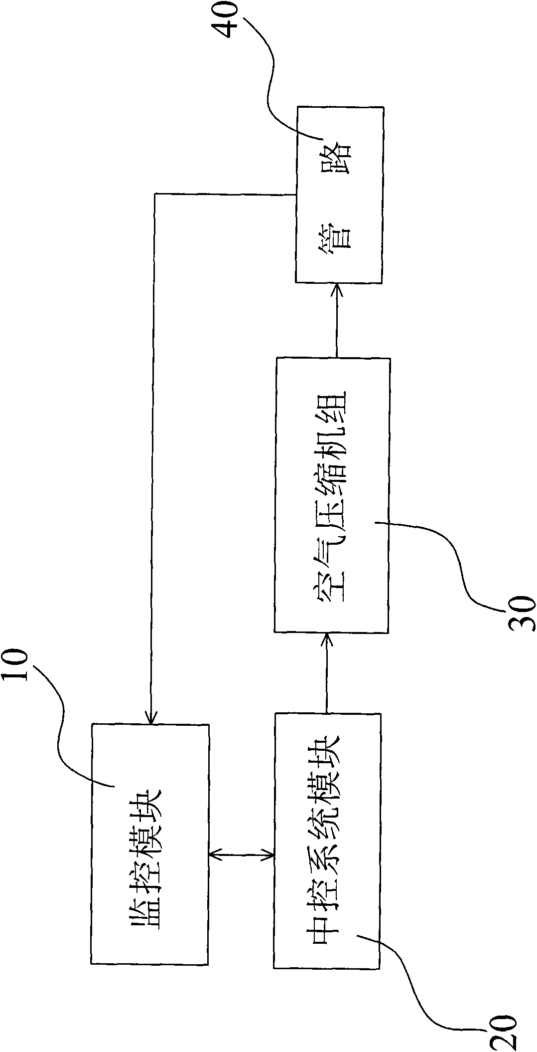
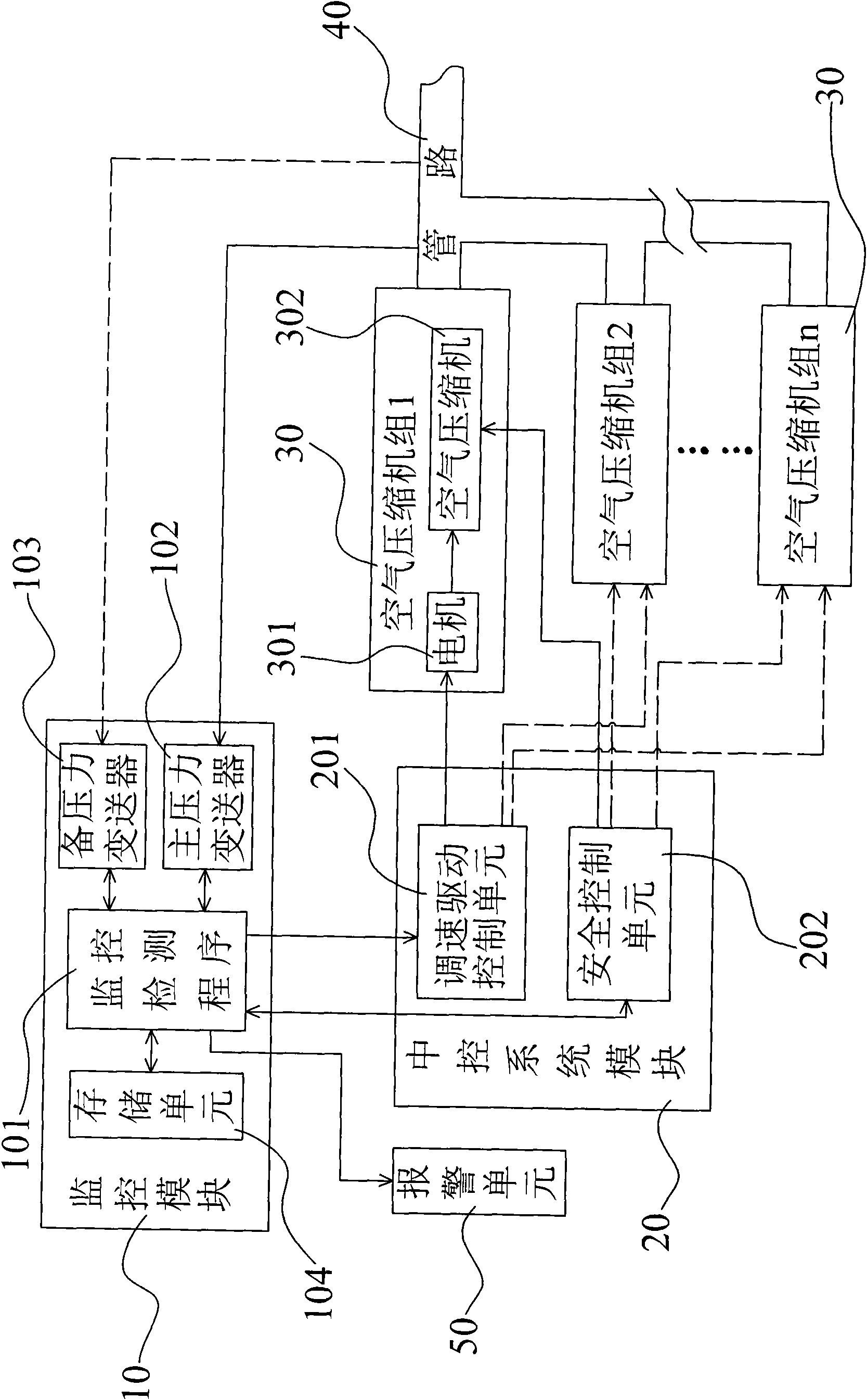
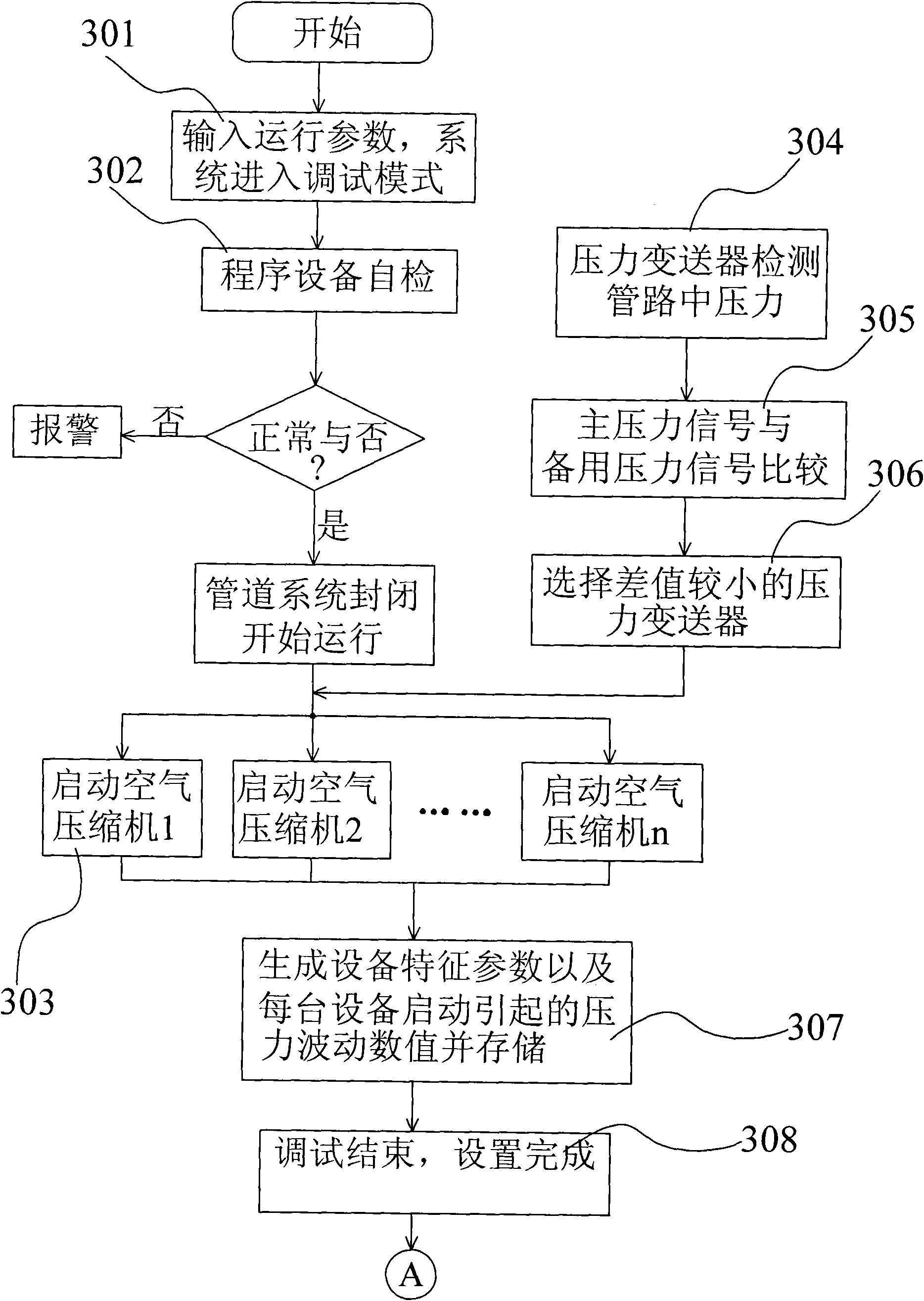
[0017] refer to figure 1 with figure 2 As shown in , the air compressor unit energy-saving control system includes a monitoring module 10, a central control system module 20, an alarm module 50 and a plurality of air compressor units 30, wherein the monitoring module 10 includes pressure detection The main pressure transmitter 102 and backup pressure transmitter 103, a monitoring and detection program 101 and a storage unit 104; the central control system module 20 includes a safety control unit 202 and a speed control drive control unit 201, and its To be respectively connected to the monitoring module 10 and the air compressor unit 30; the air compressor unit 30 is composed of a motor 301 and an air compressor 302, and wherein the motor 301 is respectively connected to t...


PUM


Abstract

The invention discloses a system for energy-saving control of an air compressor unit, which comprises a monitor module, a central control system module and an air compressor unit, wherein the monitor module comprises a main pressure transmitter, a spare pressure transmitter, a monitoring detection program and a storage unit; the central system module is connected with the monitor module and the air compressor unit respectively and comprises a safety control unit and a regulation speed drive control unit; and the air compressor unit consists of a motor and an air compressor, the motor is connected with the regulation speed drive control unit and the air compressor respectively, and the air compressor is connected with the safety control unit and a pipeline. The monitor module detects the pressure in the pipeline and processes data detected in time to allow the central system module to regulate and control the air compressor unit according to pressure trend analysis. The invention has the advantages of diagnosing pressure change trend and making quick and timely response to possible pressure loss, thereby saving energy.

Description

technical field [0001] The invention relates to a frequency conversion system, in particular to a frequency conversion system for energy saving of an air compressor. Background technique [0002] With the promotion of frequency converters, various energy-saving products have emerged one after another. At present, the most common method is to use the self-tuning function of the PID secondary table to control the output frequency of the frequency converter to achieve the effect of speed regulation, so as to achieve energy saving. purpose, but this control method is more effective for stable working conditions, but most of the compressed air is not used in a stable state, which will cause system instability and insufficient air outlet pressure. If the user wants to get rid of the above This situation can only increase the set target pressure, but, in this case, the effect of energy saving is lost. [0003] In addition, pressure transmitters and microcomputer controllers are us...

Claims


Application Information

Patent Timeline
IPC IPC(8): F04B49/02F04B49/08F04C28/02F04C28/06G05B19/048
Inventor 白俊钢田其宇姜举
Owner BEIJING FENGDY S&T
Learn More