Revolving frictional generator

A technology of rotating friction and generator, applied in the direction of friction generator, etc., can solve the problems of inconvenience of portability, price dependence, high cost, and achieve the effect of simple structure, low cost and light weight

Inactive Publication Date: 2009-09-09
NORTH CHINA ELECTRIC POWER UNIV (BAODING)
View PDF0 Cites 44 Cited by
  • Summary
  • Abstract
  • Description
  • Claims
  • Application Information

AI Technical Summary

Problems solved by technology

Conventional generators rely on electromagnetic induction to generate electricity, using a large amount of ferromagnetic materials and copper and other co

Method used


Image

  • Revolving frictional generator
  • Revolving frictional generator
  • Revolving frictional generator

Examples


Embodiment Construction

[0012] The present invention provides a rotating friction generator, and the present invention will be further described below through the description of the drawings and specific embodiments.

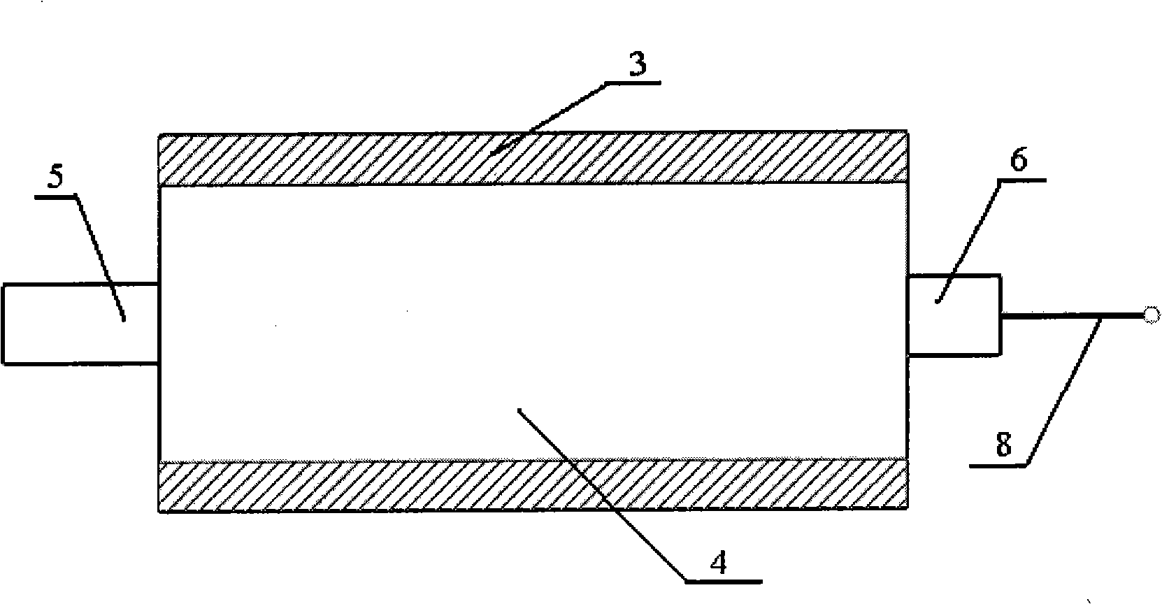
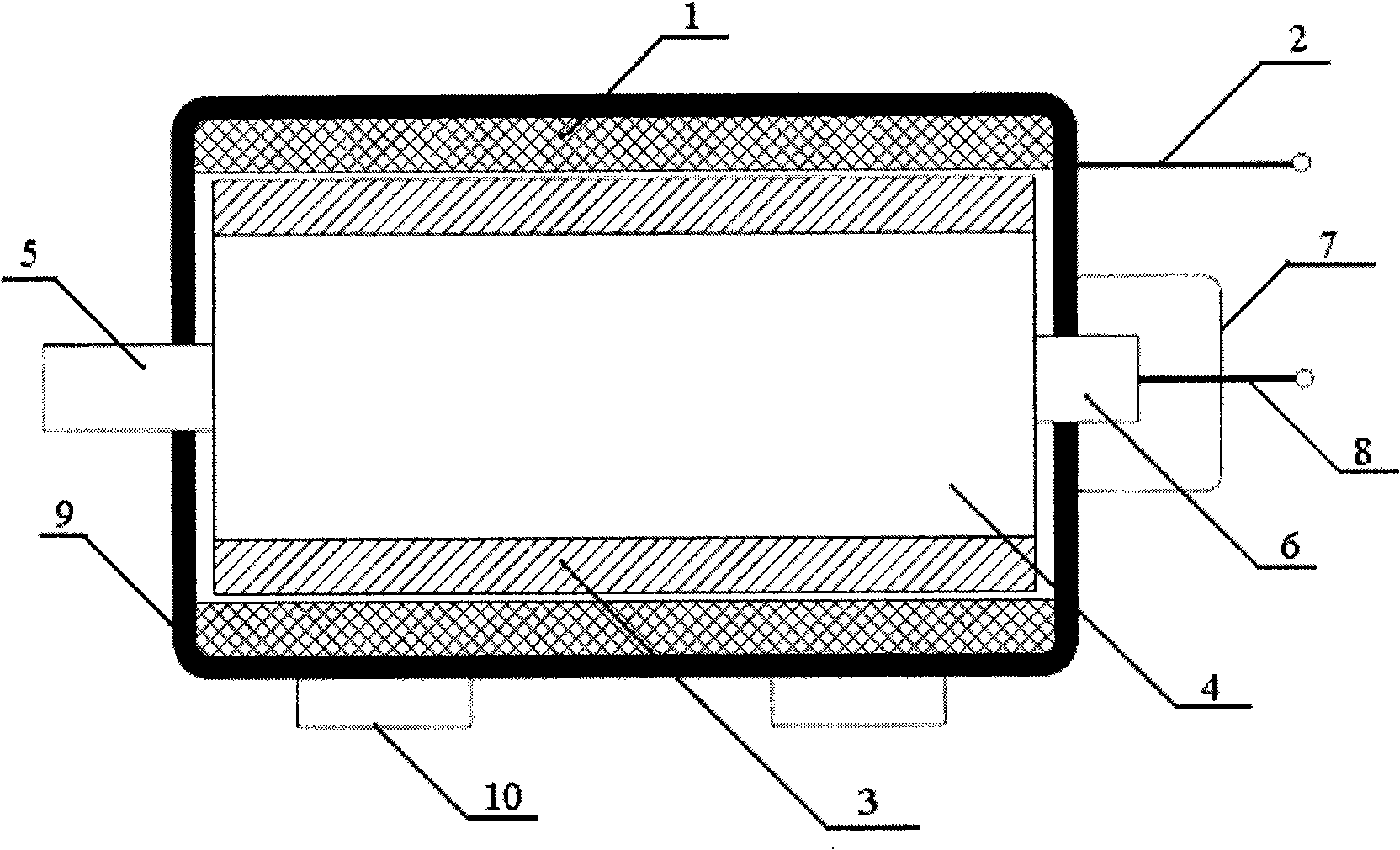
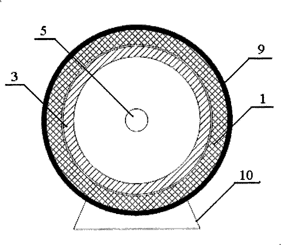
[0013] figure 1 is an axial sectional view of the main rotor structure of the rotating friction generator; figure 2 is an axial sectional view of the rotating friction generator. The stator is composed of a stator friction material layer 1 evenly fixed and distributed on the inner wall of the cylindrical shell 9 and a stator output terminal 2 fixed on the outer wall of the shell 9, wherein the stator friction material layer 1 is made of rubber and has a thickness of 15mm; The structure of the rotor is as follows: the rotor friction material layer 3 is evenly fixed and distributed on the outer wall of the cylindrical rotor shaft tube 4, and the drive shaft 5 and the collector shaft 6 are respectively fixedly installed on the axis lines of the two bottom surfaces of the rotor shaft tub...


PUM


Abstract

The invention pertains to the field of generating technology, in particular to a revolving frictional generator. The generator utilizes the phenomenon of triboelectrification to generate; a stator frictional material on the internal wall of an outer shell is closely contacted with a rotor frictional material on the external wall of a rotor shaft barrel; the rotor shaft barrel is revolved so as to cause rotary friction between the stator frictional material and the rotor frictional material and generate the current; the current is conducted out of the rotor output end. The revolving frictional generator provided by the invention has the advantages of simple structure, convenient realization and easy transportation. The revolving frictional generator is mainly used for manufacturing non-metal material and has good social and economic benefits with light weight and low cost.

Description

technical field [0001] The invention belongs to the technical field of power generation, and in particular provides a rotating friction generator. Background technique [0002] All countries in the world are facing the dual pressure of conventional energy shortage and environmental protection. The development and application of various new forms of power generation play a very important role in alleviating the current energy pressure. Many forms of new energy power generation can not pollute and damage the environment, so the development and application of new forms of power generation is of great significance to environmental protection and energy conservation. Conventional generators rely on electromagnetic induction to generate electricity, using a large amount of ferromagnetic materials and copper and other conductive materials, which are heavy and costly, and the price is also dependent on metal materials that are not abundant. Even small motors are not portable. The...

Claims


Application Information

Patent Timeline
IPC IPC(8): H02N1/04
Inventor 朱永强许郁
Owner NORTH CHINA ELECTRIC POWER UNIV (BAODING)
Why Eureka
Try Eureka