
Injector for injecting fuel

A technology of injectors and fuels, applied in fuel injection devices, special fuel injection devices, fuel injection valves driven by fluid pressure, etc., can solve problems such as damage to functions, reduce valve wear, realize motion quality, The effect of increasing the multi-spray ability

Inactive Publication Date: 2009-09-09
ROBERT BOSCH GMBH
View PDF0 Cites 6 Cited by
  • Summary
  • Abstract
  • Description
  • Claims
  • Application Information

AI Technical Summary

Problems solved by technology

wear, which impairs the function

Method used


Image

  • Injector for injecting fuel
  • Injector for injecting fuel

Examples


Embodiment Construction

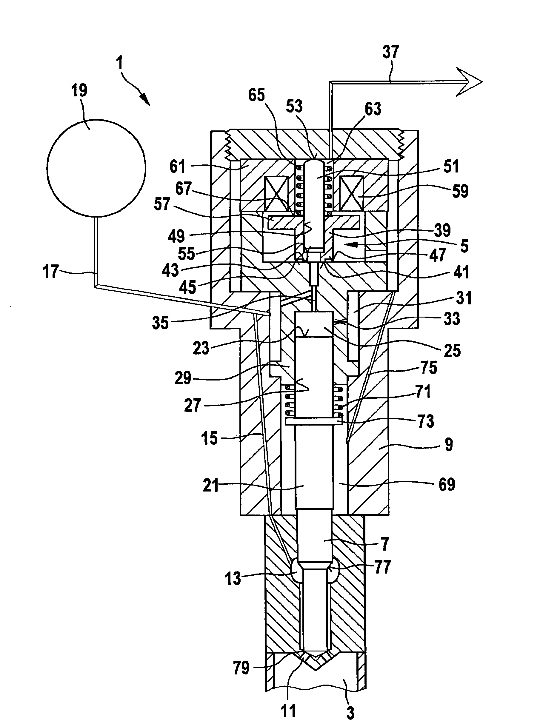
[0024] exist figure 1 A fuel injector designed according to the invention is shown in a first embodiment.

[0025] In an injector 1 for injecting fuel into a combustion chamber 3 of an internal combustion engine, a control valve 5 for controlling an injection valve element 7 is accommodated in an injector housing 9 . In order to inject fuel into the combustion chamber 3 of the internal combustion engine, the injection valve element 7 releases or closes at least one injection opening 11 . The injector element 7 is surrounded by a nozzle chamber 13 which is connected via a high-pressure line 15 to a fuel supply line 17 . A fuel supply line 17 connects a high-pressure accumulator 19 of a high-pressure accumulator injection system (common rail system) to the injector 1 .

[0026] A control piston 21 is connected to the injection valve element 7 on that side of the injection valve element 7 facing away from the at least one injection opening 11 . The control piston 21 delimits a...


PUM


Abstract

The invention relates to an injector for injecting fuel into a combustion chamber (3) of an internal combustion engine, having an injector housing (9) in which is held a control valve (5) for activating an injection valve element (7) which opens or closes off at least one injection opening (11), wherein the control valve (5) comprises a valve piston (39), by means of which a connection from a control space (25) into a fuel return line (27) can be opened or closed off. The valve piston (39) comprises an annular seat face (41) which can be placed into a seat (43). A shoulder (55; 93) is formed on the valve piston (39), which shoulder (55; 93) is arranged on the high-pressure side of the valve piston (39) in such a way that the pressure force exerted by the fuel on the shoulder (55; 93) assists the closing movement of the valve piston (39).

Description

technical field [0001] The invention relates to an injector for injecting fuel into a combustion chamber of an internal combustion engine according to the preamble of claim 1 . Background technique [0002] For the injection of fuel into the combustion chambers of self-igniting internal combustion engines, in particular of direct-injection diesel engines, stroke-controlled high-pressure accumulator systems (common rail systems) are increasingly being used. In stroke-controlled high-pressure accumulator injection systems, the injection pressure can be adapted to load and speed. [0003] In stroke-controlled fuel injectors, the injection valve element is controlled via a servo control chamber. The pressure in the servo control chamber is controlled by a solenoid valve with a spherical closing element. However, this is not pressure-balanced and requires high spring forces, high solenoid switching forces and a lot of installation space. The control by means of a ball solenoid...

Claims


Application Information

Patent Timeline
Patent Type & Authority Applications(China)
IPC IPC(8): F02M47/02F02M63/00
CPCF02M63/0015F02M47/027F02M63/0073F02M2547/003F02M2200/304F02M63/008
Inventor N·艾森门格尔H-C·马盖尔H-C·马盖尔
Owner ROBERT BOSCH GMBH
Features
  • Generate Ideas
  • Intellectual Property
  • Life Sciences
  • Materials
  • Tech Scout
  • Unparalleled Data Quality
  • Higher Quality Content
  • 60% Fewer Hallucinations
Learn More