

System for generating, converting, distributing and electrically starting on board an aircraft
A technology for power distribution and starting system, applied in electrical components, circuit devices, aircraft parts, etc., can solve problems such as adverse consequences of aircraft weight, and achieve the effect of improving power/weight ratio and reducing volume
- Summary
- Abstract
- Description
- Claims
- Application Information
AI Technical Summary
Problems solved by technology
Method used
Image

Examples
no. 1 example
[0135] A. The first example of construction options: 2P2C architecture
[0136] In a twin-engine aircraft, this "2P2C" architecture consists of the following:
[0137] - Two power distribution channels for high power loads, called "P",
[0138] - Two power distribution channels for conventional loads, called "C".
[0139] therefore Figure 4 Shows four identical starter-generators SG-B, SG-G1, SG-G2 and SG-Y, four simple rectifiers RU-B1, RU-B2, RU-Y1 and RU-Y2, four filtered reduction Inverters MCU-B1, MCU-B2, MCU-Y1 and MCU-Y2, two automatic transformers ATU-G1 and ATU-G2 and three transformer-rectifiers TRU-B, TRU-Y and TRU-G.
[0140] according to image 3 , the power drawn from the aircraft engine Eng1 or Eng2 is distributed via channel "P" and channel "C".
[0141] "P" power distribution channel B (or Y) specifically includes:
[0142] -Electric starter-generator SG-B(SG-Y)
[0143] - Main busbar, preferably 230 volts alternating current, AC-B (AC-Y), which distri...
no. 2 example
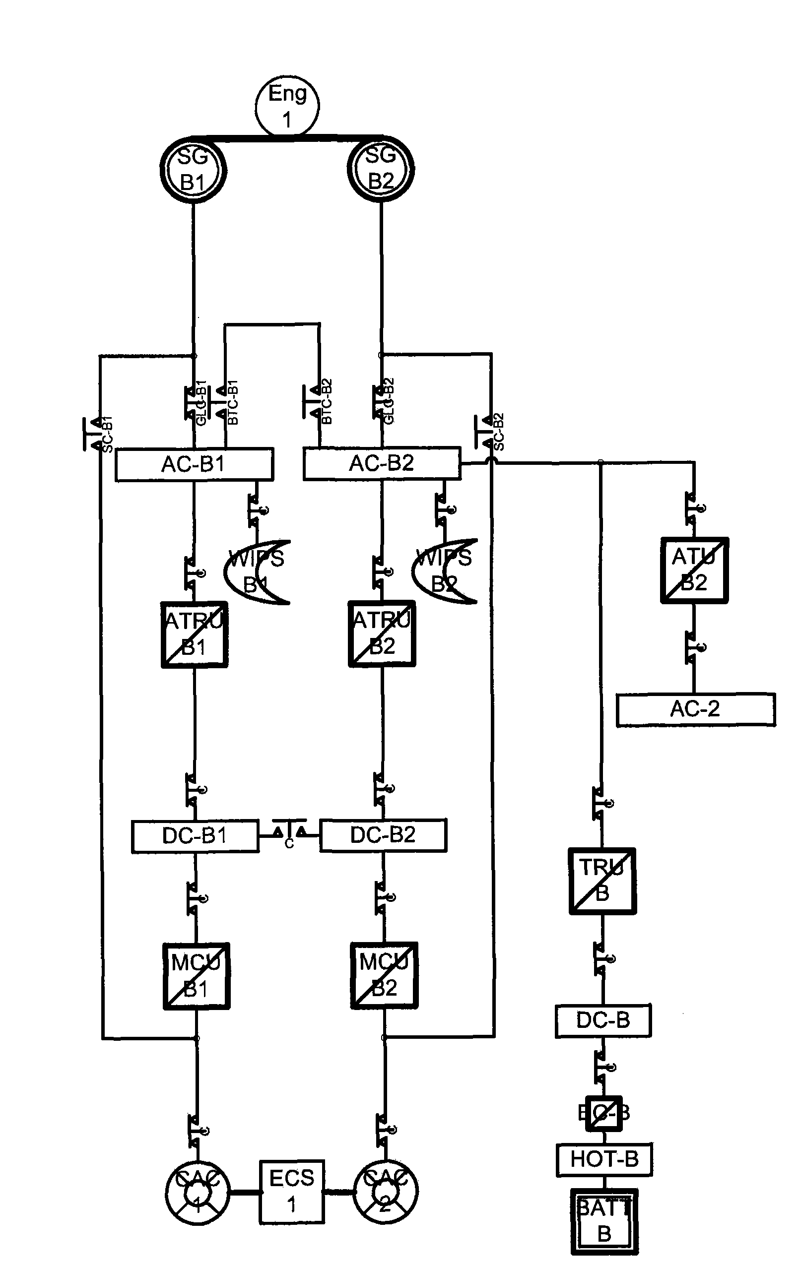
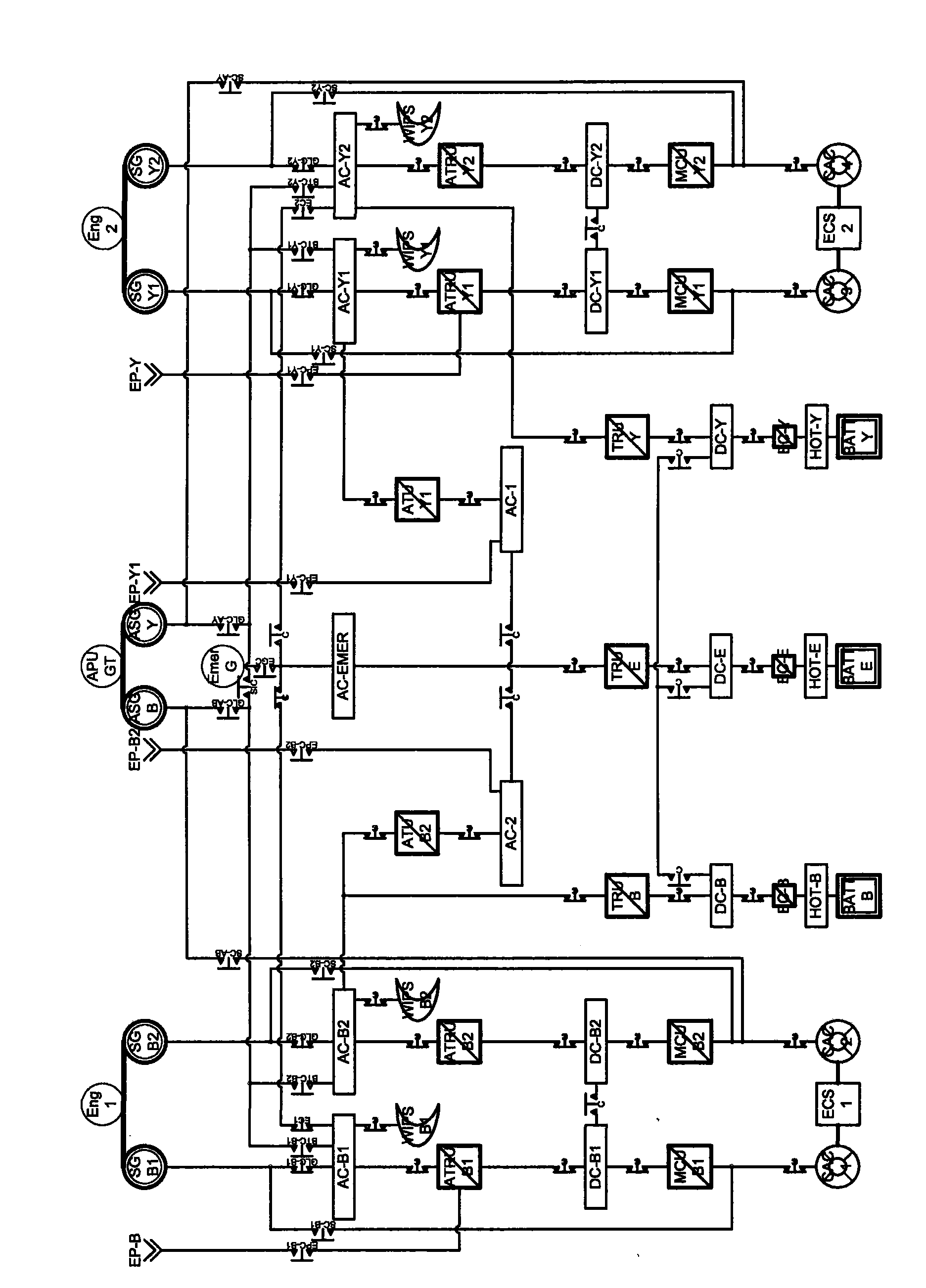
[0176] b. The second example of construction selection scheme: 4P2C architecture
[0177] In a twin-engine aircraft, the "4P2C" architecture consists of the following:
[0178] - Four power distribution channels for high power loads, called "P",
[0179] - Two power distribution channels for conventional loads, called "C".
[0180] Such as Figure 5 As shown, this example construction option includes four starter-generators SG-B1 , SG-Y1 , SG-B2 and SG-Y2 of identical capacity and two conventional generators G-G1 and G-G2. if already in Figure 4 shown in , which includes: four simple rectifiers RU-B1, RU-B2, RU-Y1, RU-Y2; four reduced filter inverters MCU-B1, MCU-B2, MCU-Y1, MCU -Y2; and two autotransformers ATU-G1 and ATU-G2.
[0181] The advantages listed for the "2P2C" architecture are also valid for the "4P2C" architecture.
[0182] In such an example, each heavily loaded "P" channel is split into two channels "B1" and "B2" (or "Y1" and "Y2"). Such a division all...
no. 3 example
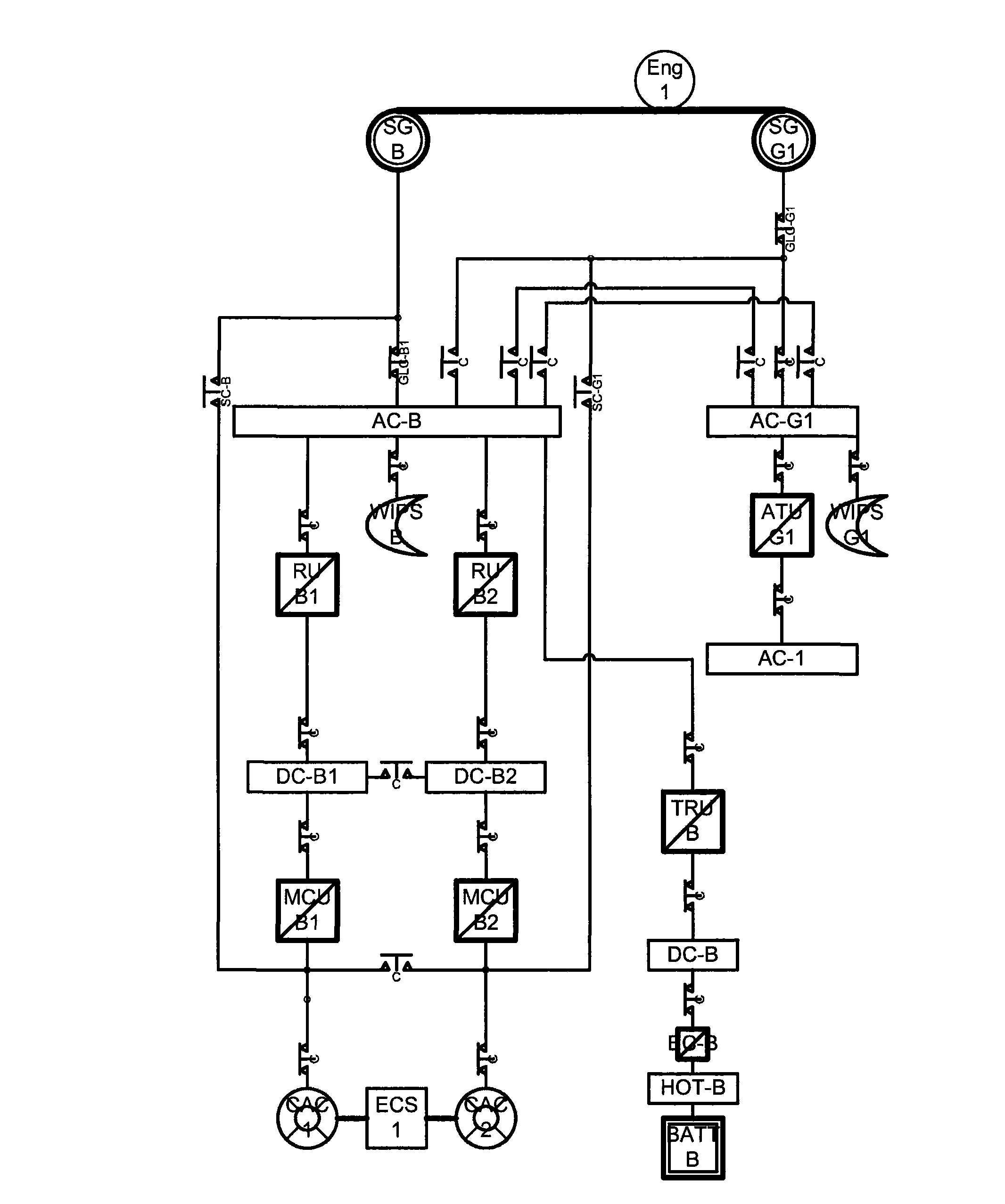
[0197] C. The third example of construction options: 4P*2C architecture
[0198] In the case of a twin-engine aircraft, the "4P*2C" architecture consists of the following:
[0199] - four power distribution channels for high power loads, denoted "P*", i.e. they include complex modifications,
[0200] - Two power distribution channels for conventional loads, shown as "C".
[0201] The advantages listed for the "4P2C" architecture also apply to the "4P*2C" architecture, except that the overall interchangeability between the 6 starter-generators does not exist in the "4P*2C" architecture, but can To compensate, there is no need for a 230VAC / 115VAC converter.
[0202] Such as Image 6 As shown, the "4P*2C" architecture includes four power starter-generators SG-B1, SG-Y1, SG-B2 and SG-Y2 and two traditional starter-generators G-G1 and G-G2 , but no autotransformer. This architecture introduces technical differences between power starter-generators and conventional generators, ...
PUM
 Abstract
Description
Claims
Application Information