Swiveling mechanism and engineering machinery with swiveling mechanism

A slewing mechanism and component technology, which is applied in the directions of earthmoving machines/shovels, cranes, building structures, etc., can solve the problem of increasing the use cost and maintenance cost of the bearing-type slewing mechanism, the low maintainability of the slewing bearing 300, and the bearing-type slewing mechanism. The high manufacturing cost of the slewing mechanism achieves the effect of strong maintainability, simple structure and low slewing resistance

Inactive Publication Date: 2009-09-16
SANY HEAVY IND CO LTD (CN)
View PDF0 Cites 8 Cited by
  • Summary
  • Abstract
  • Description
  • Claims
  • Application Information

AI Technical Summary

Problems solved by technology

However, the bearing-type slewing mechanism also has its own defects; on the one hand, the slewing bearing requires high machining accuracy, and the bearing rolling body needs to be specially processed to provide its strength, which makes its manufacturing cost very high. In turn, the manufacturing cost of the bearing-type slewing mechanism is very high. Generally speaking, under the same specification, the cost of the bearing-type slewing mechanism is 3-6 times that of the tray-type slewing mechanism; in large construction machinery, the manufacturing and production of slewing bearings More difficult, more difficult to mass produce
On the other hand, in use, a corresponding lubricating mechanism is required to maintain good lubrication of the slewing bearing 300; the maintainability of the slewing bearing 300 is low, and when a failure occurs, it is generally maintained by replacing the slewing bearing 300. This also increases the use cost and maintenance cost of the bearing type slewing mechanism
[0009] In short, the prior art cannot provide a slewing mechanism with low slewing resistance and low manufacturing and maintenance costs.

Method used


Image

  • Swiveling mechanism and engineering machinery with swiveling mechanism
  • Swiveling mechanism and engineering machinery with swiveling mechanism
  • Swiveling mechanism and engineering machinery with swiveling mechanism

Examples


Embodiment Construction

[0044] The present invention will be described in detail below in conjunction with the accompanying drawings. The description in this part is only exemplary and explanatory, and should not have any limiting effect on the protection scope of the present invention.

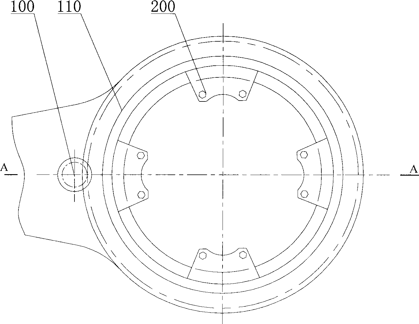
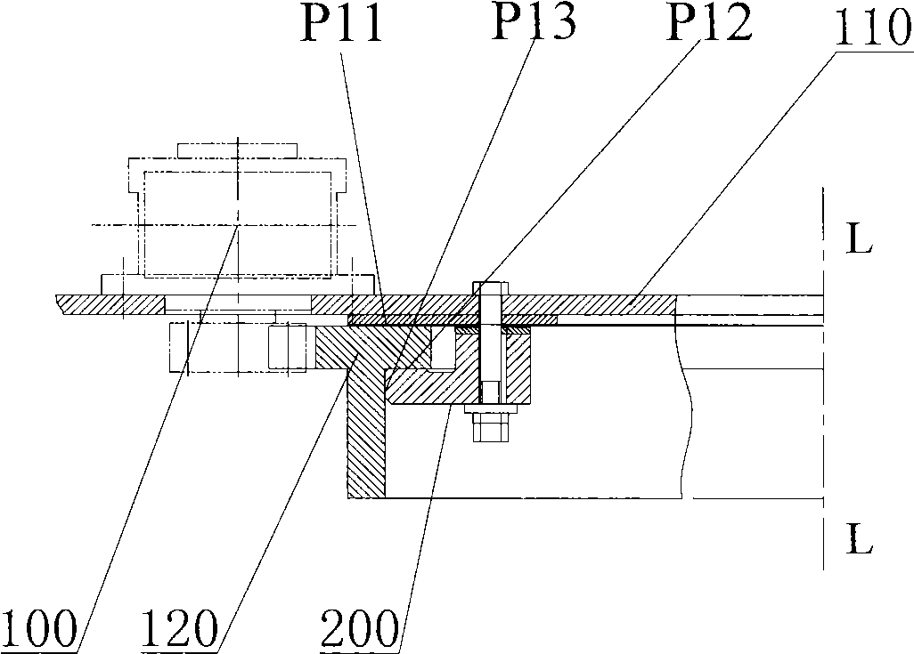
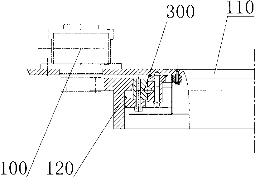
[0045] It should be noted that: in this document, the axial direction is a direction parallel to the axis of rotation of the slewing mechanism; it can be understood that the slewing mechanism provided by the present invention is not limited to horizontal arrangement, but can also be arranged vertically.

[0046] The basic idea of ​​the slewing mechanism provided by the present invention is to convert the appropriate sliding friction structure in the tray-type slewing mechanism into a rolling friction mechanism to reduce the slewing resistance; at the same time, compared with the bearing-type slewing mechanism, it has simple structure and The feature of strong maintainability facilitates the mass production and manufa...


PUM


Abstract

The invention discloses a swiveling mechanism and an engineering machinery with the swiveling mechanism. The swiveling mechanism includes a first component and a second component which can rotate reversely, the first component includes at least two roller columns, the roller column can be rotary installed on the first component body; the second component includes a center line and a ring shape curve surface coinciding with a swiveling shaft line of the swiveling mechanism, the ring shape curve surface cooperates with the roller column peripheral, preferably, a first face of the second component cooperates with a first face of the first component for forming a first cooperating surface. The roller column is rotary installed on a first component body, cooperation between the ring shape curve surface and the roller column peripheral belongs to rolling cooperation which can reduce swiveling resistance of the swiveling mechanism. Compared with the bearing type swiveling mechanism, the swiveling mechanism can reduce manufacturing and using cost. The invention provides the swiveling mechanism with little swiveling resistance, simple structure and strong maintenance from a new technique angle.

Description

technical field [0001] The invention relates to a mechanical connection mechanism, in particular to a turning mechanism, and also relates to a construction machine with the turning mechanism. Background technique [0002] As we all know, construction machinery such as excavators, cranes, concrete distribution racks and concrete pump trucks all have corresponding booms for predetermined operations; and it is also necessary to adjust the positional relationship between the boom and the chassis or chassis according to the position of the working surface. In order to facilitate the adjustment of the boom, generally a turning mechanism is provided between the boom and the chassis or the chassis, so that the boom can rotate within a range of 360 degrees relative to the chassis or the chassis. In addition, in other engineering machinery or equipment, there is also a slewing mechanism to achieve relative adjustment of the position of appropriate components. [0003] The swivel mech...

Claims


Application Information

Patent Timeline
Patent Type & Authority Applications(China)
IPC IPC(8): E02F9/10B66C23/84E04G21/04
Inventor 许小球袁国文李小锋
Owner SANY HEAVY IND CO LTD (CN)
Why Eureka
Try Eureka