Axial load resistant no-return-difference torque output ball-hinged driving mechanism

A technology of axial load and driving mechanism, which is applied in the direction of electromechanical devices, electric components, and control of mechanical energy. It can solve the problems of poor axial load resistance, large transmission clearance, and axial length and dimension changes, and achieve axial load resistance. Good performance, good transmission rigidity, good effect of no hysteresis

Inactive Publication Date: 2011-05-04
BEIHANG UNIV
View PDF0 Cites 0 Cited by
  • Summary
  • Abstract
  • Description
  • Claims
  • Application Information

AI Technical Summary

Problems solved by technology

[0004] 1) poor axial load resistance
If an elastic coupling is used as a transitional joint, the axial length dimension will change; while a cross universal coupling is used, the coupling pin bearing of the coupling is subject to axial and radial alternating loads, which is easy to wear and deform, resulting in Transmission clearance is large
[0005] 2) The rotation difference is large
If an elastic coupling is used as a transitional coupling, there is a certain phase difference between the output shaft and the input shaft; while using a cross universal coupling, the wear of the cross pin will quickly affect the rotation accuracy, so that there is a Rest zone, impact on the ball joint drive

Method used


Image

  • Axial load resistant no-return-difference torque output ball-hinged driving mechanism
  • Axial load resistant no-return-difference torque output ball-hinged driving mechanism
  • Axial load resistant no-return-difference torque output ball-hinged driving mechanism

Examples


Embodiment Construction

[0032] The present invention will be further described in detail below in conjunction with the accompanying drawings.

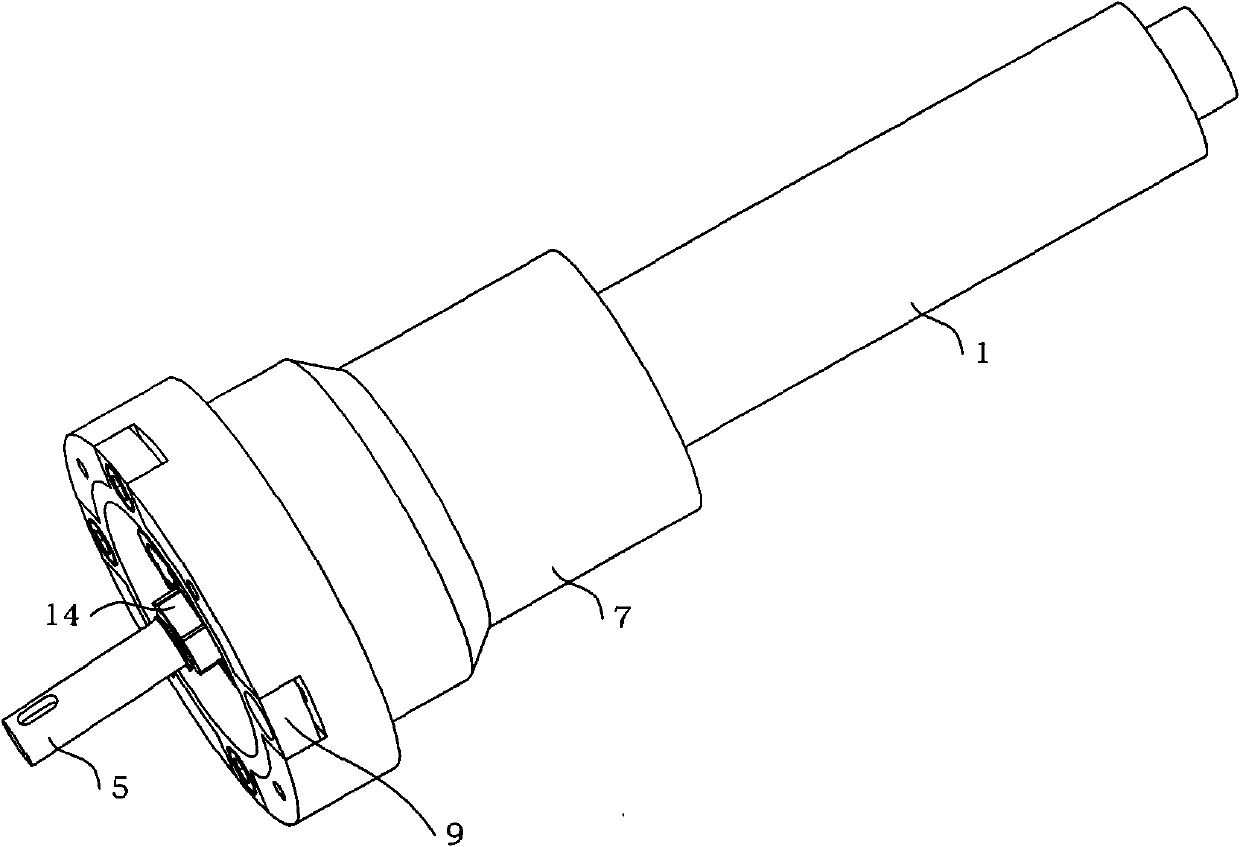
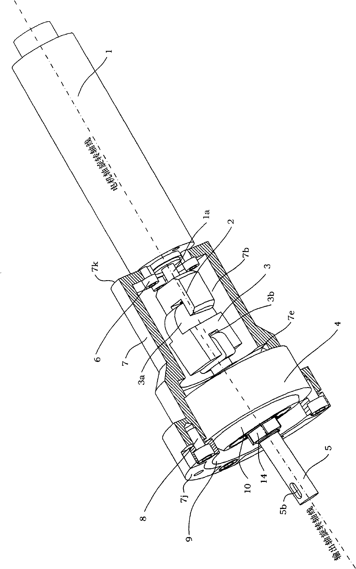
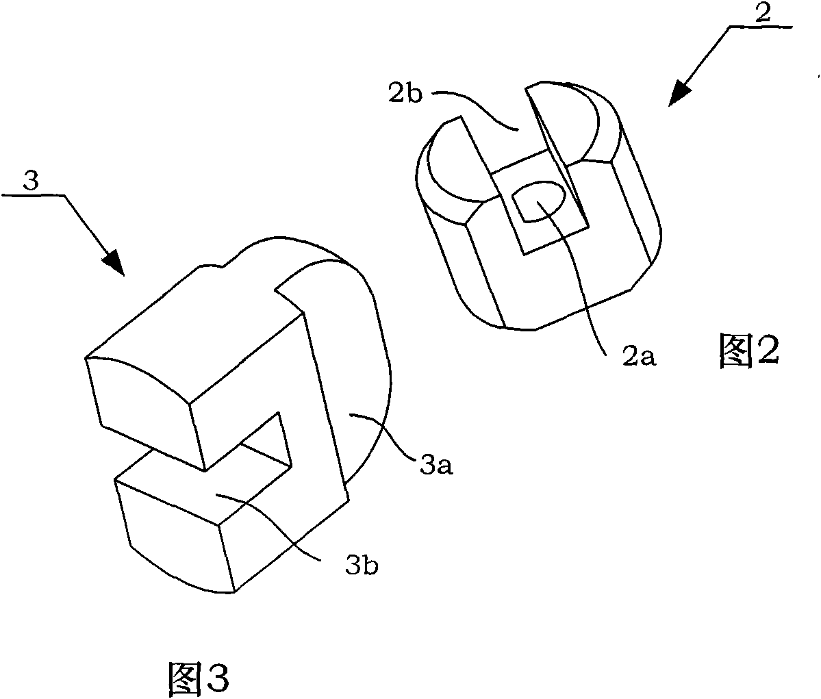
[0033] Please see figure 1 , Figure 1A As shown, an axial load-resistant non-backlash torque output spherical joint drive mechanism of the present invention includes a servo DC motor 1, a motor shaft coupling block 2, a cross slider 3, a ball joint outer ring 4, and an output shaft 5. Motor fastening screw 6, motor mounting seat 7, blank holder ring fastening screw 8, blank holder ring 9, ball joint inner ring 10, first angular contact ball bearing 11, second angular contact ball bearing 12, bearing Outer retaining ring 13, output shaft fastening nut 14.

[0034] Wherein, the drive unit is composed of a servo DC motor 1 , a motor shaft coupling block 2 , a motor fastening screw 6 and a motor mount 7 .

[0035] Wherein, the transmission unit is composed of the motor shaft coupling block 2, the cross slide block 3 and the output shaft 5.

[0036] Wherein, ...


PUM


Abstract

The invention discloses an axial load resistant no-return-difference torque output ball-hinged driving mechanism, comprising a driving unit, a transmission unit and an aligning unit; a servo direct current motor is arranged on a motor mounting seat and is connected with a motor shaft coupling block so as to form the driving unit; an output shaft, a criss-cross sliding block and the motor shaft coupling block are coupled by a longitudinal slot and a horizontal slot so as to form the transmission unit; a pressure side ring is used for fastening a ball-hinged joint outer ring in a mounting hole of the motor mounting seat and a ball-hinged joint inner ring and the ball-hinged joint outer ring are mutually matched to realize the aligning function; a bearing outer baffle ring is used for pressing two angular contact ball bearings in a bearing mounting hole of a ball-hinged joint; and the output shaft and the angular contact ball bearing are locked by fastening nuts, thus forming the aligning unit together. The axial load resistant no-return-difference torque output ball-hinged driving mechanism adopts the ball-hinged joint to realize axial load characteristic, simultaneously uses the floating criss-cross sliding block to transfer torque, overcomes return difference of the servo direct current motor when switching by forward and reverse rotation, and compensates the radial and axial errors caused by deflection of the output shaft.

Description

technical field [0001] The present invention relates to a ball joint driving mechanism, more particularly, a ball joint driving mechanism with anti-axial load and non-backlash torque output. Background technique [0002] The torque output spherical hinge drive mechanism is a form of a rotary drive mechanism with an adjustable output shaft angle. When the mechanism outputs torque, the angle of the output shaft can be adjusted to adapt to changes in the posture and position of the rear transmission mechanism, and can be used in the fields of robots, micro-manipulation, medical equipment, and scientific research instruments. [0003] The traditional torque output spherical joint drive mechanism mainly uses a cross cardan coupling or an elastic coupling to connect with the output shaft to realize the functions of torque output and passive swing around the center of the ball. The realization of this kind of mechanism adopts standard devices, which has the advantages of simple an...

Claims


Application Information

Patent Timeline
Patent Type & Authority Patents(China)
IPC IPC(8): H02K7/10
Inventor 王巍于文鹏李宗良李雄峰宗光华
Owner BEIHANG UNIV
Why Eureka
Try Eureka