Electronic-control anti-backlash gear pair

A technology of gear pairs and gears, applied in the field of gear meshing pairs, can solve the problems of high control synchronization, complex structure and assembly, and relatively high requirements, so as to reduce the driving energy, the structure is simple, and the tooth flank can be eliminated or reduced. The effect of gap and hysteresis

Active Publication Date: 2015-01-21
CHONGQING UNIV
View PDF7 Cites 6 Cited by
  • Summary
  • Abstract
  • Description
  • Claims
  • Application Information

AI Technical Summary

Problems solved by technology

[0004] The gear transmission mainly affects the accuracy of the backlash, and there are many ways to adjust or eliminate the backlash, but all of them have complex structures and assemblies, which are only applicable to low-power systems, and often can only eliminate a certain constant backlash. Disadvantages: Among them, the double-drive chain anti-backlash method driven by dual motors and the auxiliary torque motor loading method introduce motors for gap adjustment, and the gap adjustment effect is relatively ideal, but there are shortcomings of large space occupation and waste of driving energy, and the cost is relatively high. High, the requirements for the control system are also relatively high, the requirements for the synchronization of the control are very high, and the drive energy is increased

Method used


Image

  • Electronic-control anti-backlash gear pair
  • Electronic-control anti-backlash gear pair
  • Electronic-control anti-backlash gear pair

Examples


Embodiment Construction

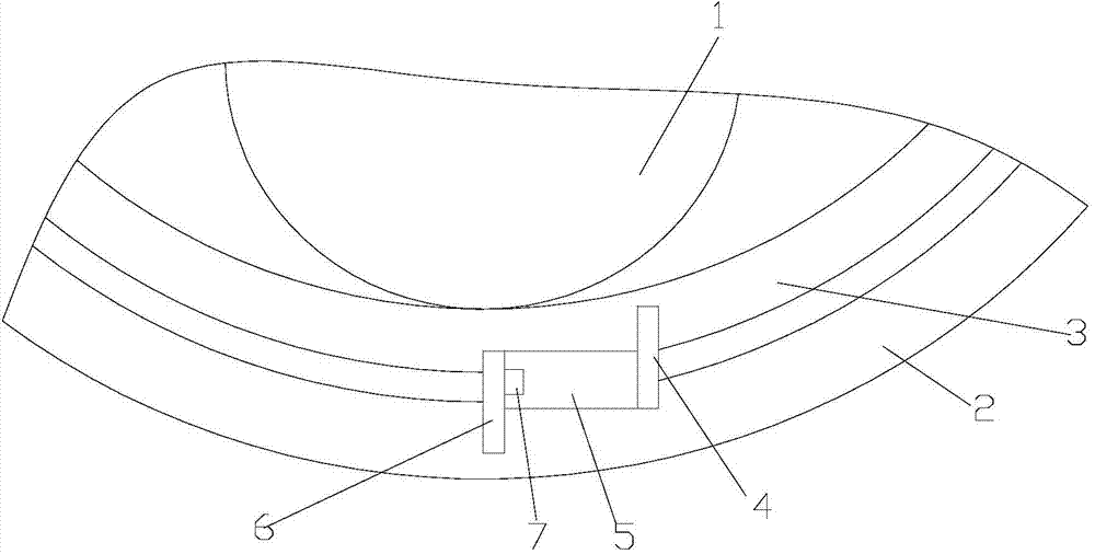
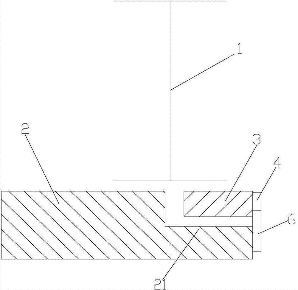
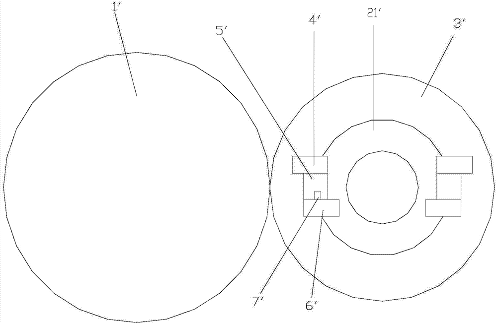
[0023] figure 1 It is a schematic diagram of the internal gear structure of the present invention, figure 2 for figure 1 Side view structural schematic diagram, image 3 It is a schematic diagram of the meshing structure of the external gear of the present invention, Figure 4 for image 3 Side view structural schematic diagram, Figure 5 It is a block diagram of the control principle, as shown in the figure: the electronically controlled backlash-eliminating gear pair in this embodiment includes gear I1, gear II2 and gear III3. The gear II2 and gear III3 are coaxially juxtaposed and mesh with gear I1, so The above-mentioned gear II2 and gear III3 have relative rotational degrees of freedom in the circumferential direction; that is, gear II2 and gear III3 constitute a double gear that meshes with gear I1, but there is a certain degree of rotational freedom between gear II2 and gear III3. Forming the possibility of mutual rotation to eliminate meshing backlash when backla...


PUM


Abstract

The invention discloses an electronic-control anti-backlash gear pair. The electronic-control anti-backlash gear pair comprises a first gear, a second gear and a third gear. The second gear and the third gear are coaxial and parallel and are meshed with the first gear, and the freedom degree of relative rotation in the circumferential direction exists between the second gear and the third gear. The electronic-control anti-backlash gear pair further comprises an electronic-control anti-backlash system composed of an electronic driving block and a control unit, wherein the electronic driving block is used for driving the second gear and the third gear to relatively rotate to eliminate meshed backlash between the second gear and the first gear and between the third gear and the first gear during electronic deformation. According to the electronic-control anti-backlash gear pair, when the backlash needs to be adjusted, electronic deformation materials are electrified to be deformed, a double gear formed by the second gear and the third gear relatively rotates to eliminate the backlash between the second gear and the first gear meshed with the second gear and between the third gear and the first gear meshed with the third gear, the gear backlash and the return difference can be accordingly eliminated or reduced in real time, cost is low, the structure is simple, accessory equipment such as a motor is not needed, the occupied space is small, driving energy is reduced, the transmission error during direction changing is reduced, and operation and control are simpler and more convenient; as the original mode that the backlash is eliminated through mechanical force of a power source is not adopted, controllability and accuracy are high, and the electronic-control anti-backlash gear pair is suitable for occasions with the requirements for the high accuracy.

Description

technical field [0001] The invention relates to a gear meshing pair, in particular to a variable-tooth-thickness gear meshing pair used for backlash elimination by electronically controlled mechanical external force. Background technique [0002] Gear transmission is used to transmit motion and force between two shafts. Compared with other mechanical transmission methods, gear transmission has stable movement, compact structure, low noise and high transmission efficiency. It is widely used in various machines and instruments. Applications. [0003] With the development of science and technology and production technology, as well as people's high-quality requirements for various products, especially in the development of precision transmission, higher and higher requirements are placed on the adjustment and control of transmission accuracy and tooth backlash. [0004] Gear transmission mainly affects the accuracy of the backlash, and there are many ways to adjust or eliminat...

Claims


Application Information

Patent Timeline
Patent Type & Authority Applications(China)
IPC IPC(8): F16H55/18
CPCF16H55/18
Inventor 王光建邹帅东
Owner CHONGQING UNIV
Why Eureka
Try Eureka