
Vapor compression refrigerating cycle apparatus

A technology for compressing refrigeration and circulation devices, applied in compressors, compressors with multiple evaporators, fluid circulation arrangements, etc. The increase of the injector pressure is easy to reduce and other problems

Inactive Publication Date: 2009-09-16
DENSO CORP
View PDF1 Cites 9 Cited by
  • Summary
  • Abstract
  • Description
  • Claims
  • Application Information

AI Technical Summary

Problems solved by technology

Due to this, the nozzle efficiency tends to decrease, and the increase in pressure by the injector also tends to decrease
Therefore, it is difficult to effectively obtain the improvement of the COP of the refrigerating cycle device

Method used


Image

  • Vapor compression refrigerating cycle apparatus
  • Vapor compression refrigerating cycle apparatus
  • Vapor compression refrigerating cycle apparatus

Examples


no. 1 example

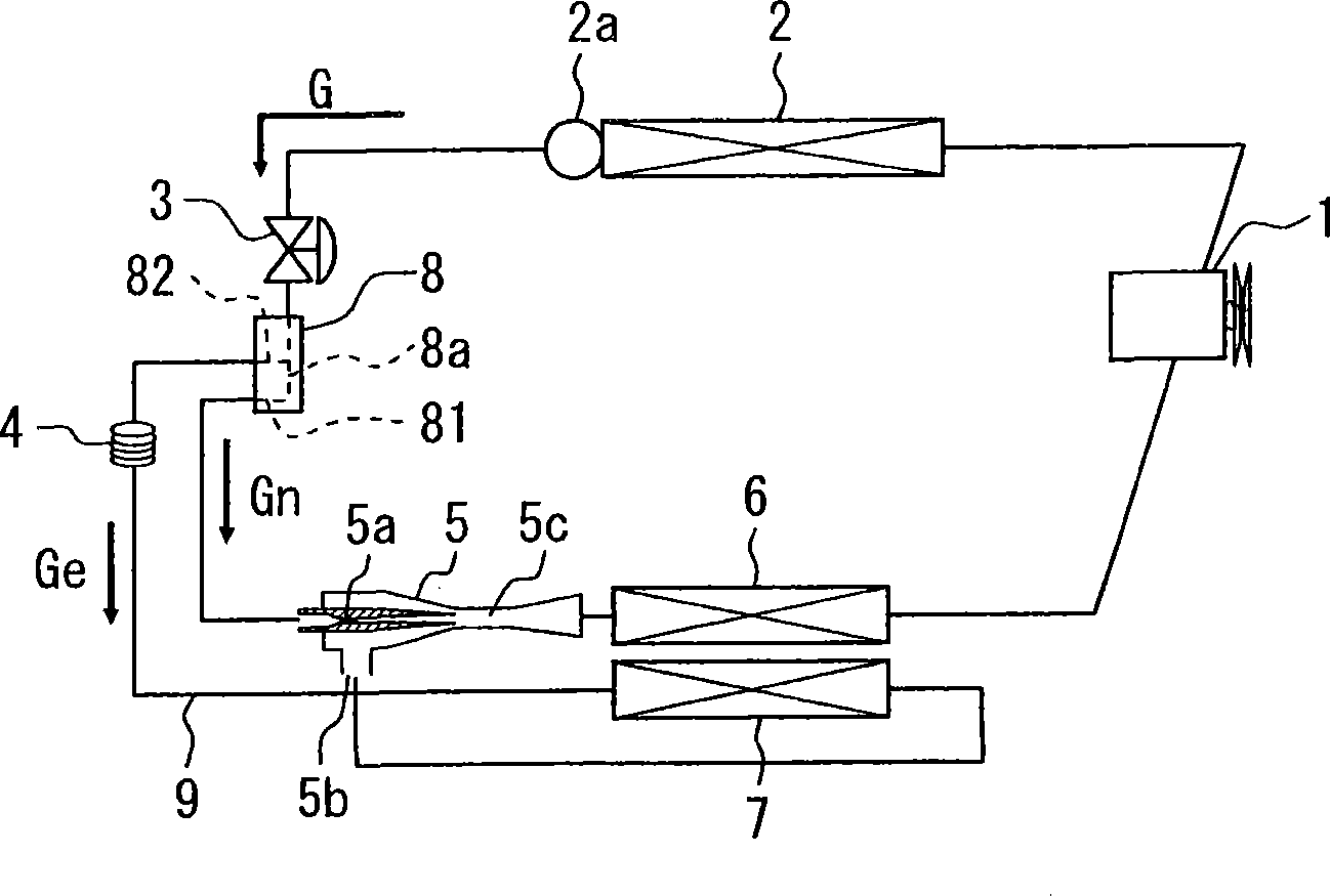
[0020] The following will refer to Figure 1 to Figure 5 A first embodiment of the present invention is described. figure 1 The vapor compression refrigeration cycle of the first embodiment is shown. The vapor compression refrigeration cycle device can be installed in vehicles for air conditioning, for example.

[0021] A vapor compression refrigeration cycle device generally includes a compressor 1, a radiator 2, a receiver 2a, a first throttle device 3, a flow distributor 8, an ejector 5, a first evaporator 6, a second evaporator 7 and a second evaporator Two throttling devices 4. The compressor 1, the radiator 2, the receiver 2a, the first throttle device 3, the flow distributor 8, the ejector 5 and the first evaporator 6 are connected in a loop form through refrigerant pipes. The refrigeration cycle device also includes a suction channel 9 branching from the flow distributor 8 and connected to the ejector 5 . The second throttle device 4 and the second evaporator 7 ar...


PUM


Abstract

The invention provides a vapor compression refrigerating cycle apparatus includes a compressor, a radiator, first and second throttle devices, a flow distributor, an ejector, a suction passage, and first and second evaporators. The flow distributor separates refrigerant decompressed through the first throttle device into a first passage and a second passage. The first passage is in communication with a nozzle portion of the ejector. The second passage is in communication with a suction portion of the ejector through the suction passage. The second throttle device and the second evaporator are disposed on the suction passage. The flow distributor is configured to be capable of adjusting a ratio of a flow rate of refrigerant passing through the second passage to a flow rate of refrigerant passing through the first passage in accordance with a heat load of at least one of the radiator, the first evaporator and the second evaporator.

Description

technical field [0001] The present invention relates to a vapor compression refrigeration cycle apparatus having an ejector as a refrigerant decompression and circulation device. Background technique [0002] In a vapor compression refrigeration cycle device, it is known to employ an ejector as a refrigerant depressurization device for decompressing a refrigerant that has been compressed into a supercritical state by a compressor and passed through Radiator cooling. The injector is, for example, that described in Japanese application JP-A-2004-116807. [0003] The ejector has a nozzle portion that converts pressure energy of refrigerant flowing from the radiator into velocity energy, thereby isentropically decompressing and expanding the refrigerant. In addition, the ejector sucks gas-phase refrigerant from the evaporator by means of a high-speed jet flow of refrigerant from the nozzle portion, and mixes the sucked refrigerant with refrigerant injected from the nozzle port...

Claims


Application Information

Patent Timeline
Patent Type & Authority Applications(China)
IPC IPC(8): F25B5/00
CPCF25B2500/19F25B41/00F25B2341/0011
Inventor 山田悦久西岛春幸尾形豪太五丁美歌茅野健太
Owner DENSO CORP
Learn More