

Global nonlinear inductance test method of switched reluctance motor
A technology of switched reluctance motor and test method, which is applied in the direction of motor generator test, measurement of resistance/reactance/impedance, measurement device, etc., can solve the problem of large inductance error of switched reluctance motor, and achieves simple measurement method and measurement accuracy high effect
- Summary
- Abstract
- Description
- Claims
- Application Information
AI Technical Summary
Problems solved by technology
Method used
Image

Examples
specific Embodiment approach 1
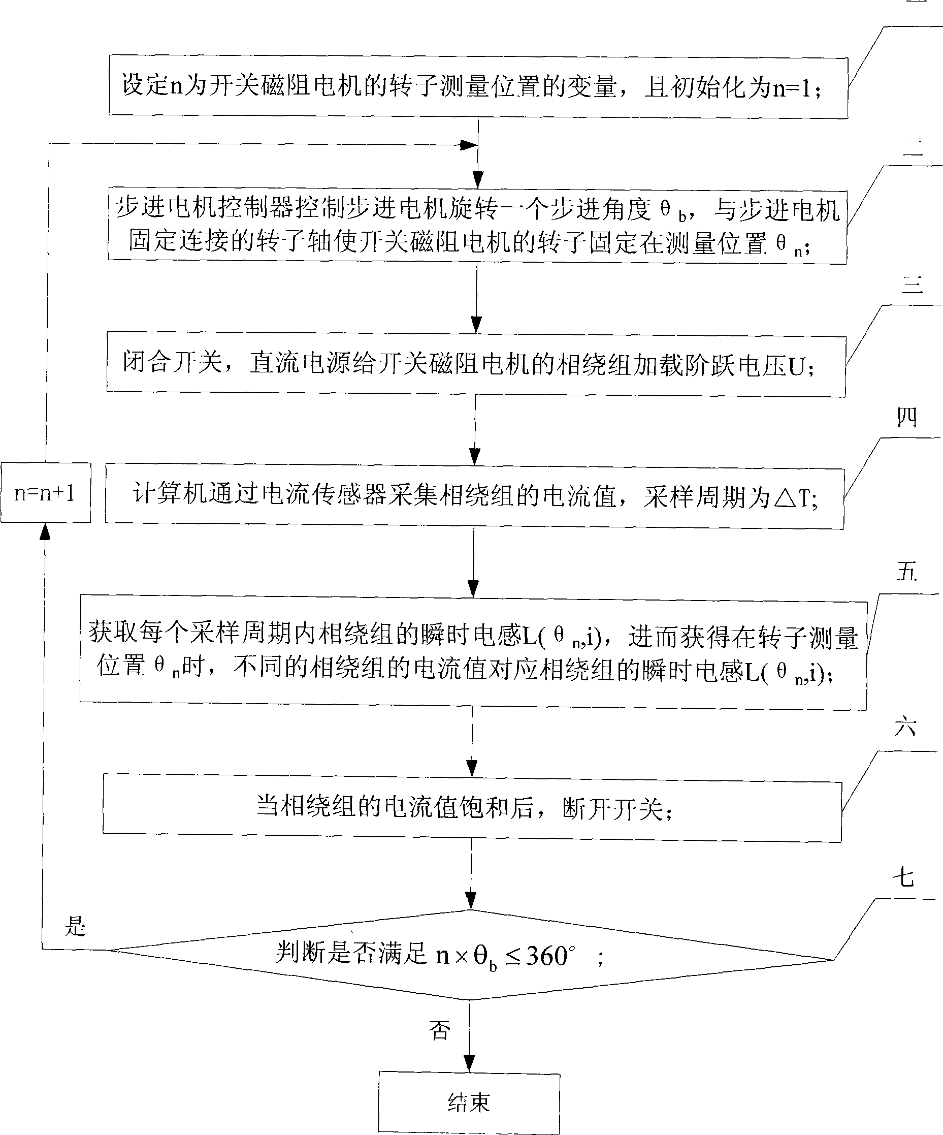
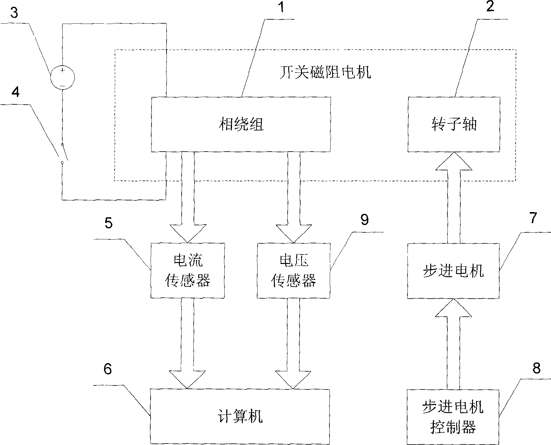
[0022] Specific implementation mode one: the following combination Figure 1 to Figure 5 Describe this embodiment, the device used in the method of this embodiment includes a switched reluctance motor, a DC power supply 3, a switch 4, a current sensor 5, a computer 6, a stepper motor 7 and a stepper motor controller 8, and the phase of the switched reluctance motor The positive input terminal of the power supply of the winding 1 is connected to the positive terminal of the DC power supply 3, the negative terminal of the DC power supply 3 is connected to one end of the switch 4, and the other end of the switch 4 is connected to the negative input terminal of the power supply of the phase winding 1,
[0023] The current sensor 5 collects the current of the phase winding 1 and outputs it to the computer 6,
[0024] The output terminal of the stepper motor controller 8 is connected with the control terminal of the stepper motor 7, and the output shaft of the stepper motor 7 is fix...
specific Embodiment approach 2
[0056] Embodiment 2: The difference between this embodiment and Embodiment 1 is that it also includes a voltage sensor 9, which collects the voltage of the phase winding 1 and outputs it to the computer 6. Others are the same as Embodiment 1.
[0057] The voltage sensor 9 monitors whether the voltage value loaded on both ends of the phase winding 1 is normal.
specific Embodiment approach 3
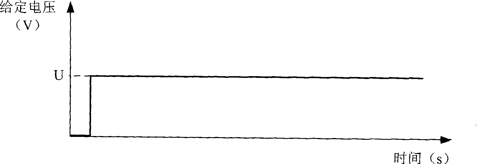
[0058] Embodiment 3: The difference between this embodiment and Embodiment 1 is that the step voltage U=1.2I described in step 3 e R, where I e R is the rated current of the phase winding 1, R is the equivalent resistance of the phase winding 1, and the others are the same as the first embodiment.
[0059] It is better to set the voltage value loaded on both ends of the phase winding 1 in this way, and the motor will not be burned.
PUM
 Abstract
Description
Claims
Application Information