Eureka AIR delivers breakthrough ideas for toughest innovation challenges, trusted by R&D personnel around the world.

Liquid crystal display device and drive method thereof

A technology of a liquid crystal display device and a driving method, applied to static indicators, color signal processing circuits, instruments, etc., capable of solving problems such as signal distortion, inability to adjust and improve panel brightness uniformity, poor panel brightness uniformity, etc.

Inactive Publication Date: 2009-09-16
INNOLUX CORP
View PDF0 Cites 4 Cited by
  • Summary
  • Abstract
  • Description
  • Claims
  • Application Information

AI Technical Summary

Problems solved by technology

[0002] With the increase of the size of the panel, coupled with the influence of the temperature of the high and low voltage end and the brightness of the lamp, when the panel is at a low gray level, the naked eye can observe the phenomenon that the sides of the panel are brighter but the center of the panel is darker. The brightness uniformity of the panel is obviously poor when the temperature is high; and with the increase of the panel size and resolution, the uneven change of the process component spacing (cell gap), and the increase of the frame frequency (120Hz), the amount of data increases, The time for data processing is shortened and the impact of resistive-capacitive loading (RC loading) on ​​the panel is more serious for signal distortion, resulting in poor brightness uniformity of the panel.
[0003] To address this phenomenon, optical engineers could only make special modifications to the scanning waveform, such as reducing the height of the scanning waveform by reducing the positive gate voltage (gate high-voltage, VGH) and chopping angle, so that the bilateral scanning drives the charging of the input terminal. It is not enough to reduce the brightness and reduce the brightening phenomenon on both sides of the panel at low gray levels, but there is still a certain difference in the brightness between the center of the panel and the two sides; and this method will also indirectly affect the charging of the middle area, because generally Generally speaking, the greater the positive gate voltage, the greater the drain current of the thin film transistor, and the faster the charging speed, and there will be less phenomenon of insufficient charge or lower transmittance. Therefore, if the positive gate voltage is lowered, the Insufficient charging in the middle area; so in order not to have too much impact on the overall transmittance, there is still a certain limit to reducing the positive gate voltage and chopping angle
[0004] In addition, white balance and overdrive are generally adjusted, but because only one set of white balance codes and one set of overdrive values ​​are used to adjust the brightness of the entire panel, it is impossible to adjust and improve the overall brightness uniformity of the panel.

Method used


Image

  • Liquid crystal display device and drive method thereof
  • Liquid crystal display device and drive method thereof
  • Liquid crystal display device and drive method thereof

Examples


Embodiment Construction

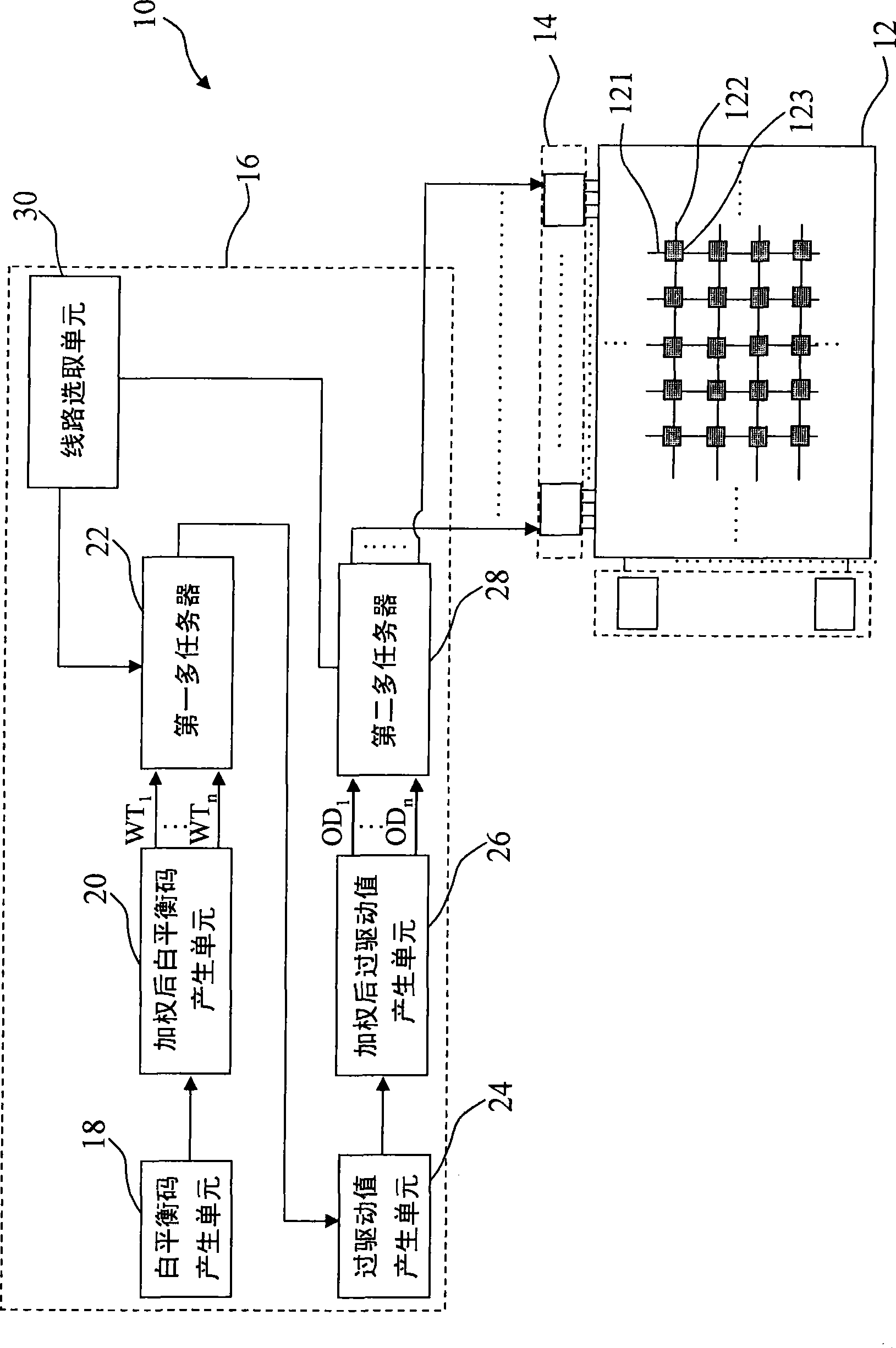
[0015] The liquid crystal display device and its driving method disclosed in the present invention can adjust the image signal provided to each pixel unit of the liquid crystal panel to achieve the purpose of improving the brightness uniformity of the liquid crystal panel.

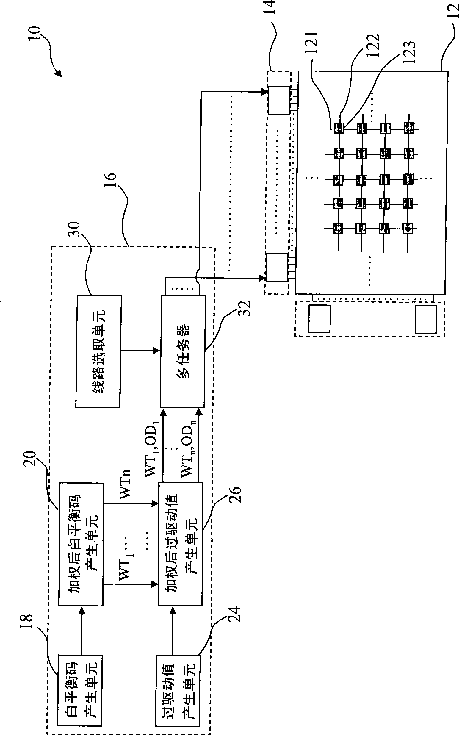
[0016] The liquid crystal display device of the present invention has two kinds of implementation modes, wherein the first embodiment is such as figure 1 As shown, the liquid crystal display device 10 includes a liquid crystal panel 12, a driving unit 14, and an image processing unit 16. The liquid crystal panel 12 has data lines 121 and scanning lines 122 perpendicular to each other and pixel units 123 located at the interlaced positions of the two. The driving unit 14 is coupled to the data line 121 and the image processing unit 16 .

[0017] Wherein, the image processing unit 16 includes a white balance code generation unit 18, a weighted white balance code generation unit 20 coupled to the white balanc...


PUM


Abstract

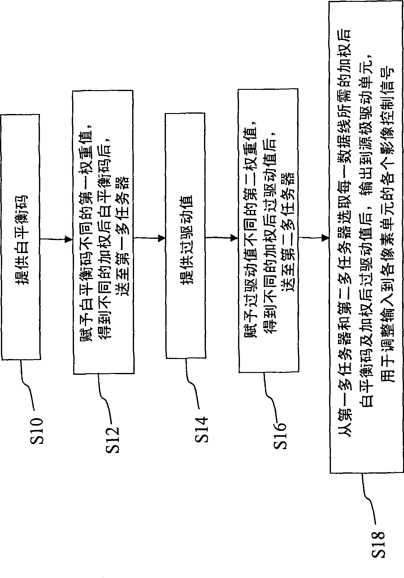
The invention relates to a liquid crystal display device and a drive method thereof, which can supply different weighted white balanced codes and weighted over driven values aiming at each data wire and amend each image signal supplied to each pixel unit in a liquid crystal panel by matching with drive units with the same or different resistance values. Therefore, the invention not only can improve the uniformity of brightness of the liquid crystal panel, but also has no effect on transmittivity even under the condition of insufficient charging.

Description

technical field [0001] The invention relates to an image signal compensation technology of a liquid crystal display device, in particular to a liquid crystal display device capable of improving the brightness uniformity of a liquid crystal panel and a driving method thereof. Background technique [0002] With the increase of the size of the panel, coupled with the influence of the temperature of the high and low voltage end and the brightness of the lamp, when the panel is at a low gray level, the naked eye can observe the phenomenon that the sides of the panel are brighter but the center of the panel is darker. The brightness uniformity of the panel is obviously poor when the temperature is high; and with the increase of the panel size and resolution, the uneven change of the process component spacing (cell gap), and the increase of the frame frequency (120Hz), the amount of data increases, The time for data processing is shortened, and the impact of resistive-capacitive lo...

Claims


Application Information

Patent Timeline
IPC IPC(8): G09G3/36H04N9/73
Inventor 康志聪黄吉廷
Owner INNOLUX CORP
Why Eureka
Eureka Blog
Learn More