High-pressure discharge lamp, manufacturing method thereof and light irradiation device

A technology of high-pressure discharge lamps and discharge tubes, which is applied to the manufacture of gas discharge lamp parts, ships, or lead-in wires, and can solve problems such as individual differences, inability to reliably obtain stable output, and difficulty in forming a hollow layer 85, etc., to achieve Reduces cooling effect

Active Publication Date: 2009-09-16
USHIO DENKI KK
View PDF1 Cites 7 Cited by
  • Summary
  • Abstract
  • Description
  • Claims
  • Application Information

AI Technical Summary

Problems solved by technology

[0009] However, according to the above structure, although it is possible to prevent the portion of the glass tube portion 81 located around the electrode from being overcooled, it is difficult to form the hollow layer 85, and individual differences are likely to occur, so there is a problem that stable output cannot be reliably obtained.

Method used


Image

  • High-pressure discharge lamp, manufacturing method thereof and light irradiation device
  • High-pressure discharge lamp, manufacturing method thereof and light irradiation device
  • High-pressure discharge lamp, manufacturing method thereof and light irradiation device

Examples


no. 1 approach

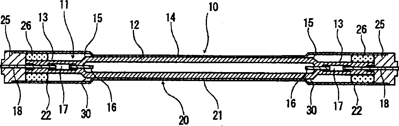
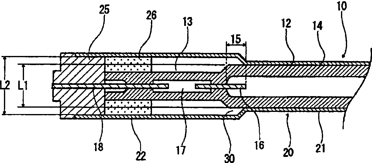
[0037] The high-pressure discharge lamp according to the first embodiment is configured by adopting a specific structure as the outer tube so that a gap extending over the entire circumference is formed between the outer peripheral surface of the portion around the electrodes of the discharge tube and the inner peripheral surface of the outer tube. Hereinafter, the configuration of the high-pressure discharge lamp according to the first embodiment will be specifically described.

[0038] figure 1 It is an explanatory cross-sectional view showing an outline of the configuration of an example of the high-pressure discharge lamp according to the first embodiment of the present invention. figure 2 yes means figure 1 An enlarged sectional view of the main part of the high pressure discharge lamp shown.

[0039] The high-pressure discharge lamp 10 is composed of the following two parts: a rod-shaped discharge tube 11 as a whole, sealed at both ends, and inside a straight tube-s...

no. 2 approach

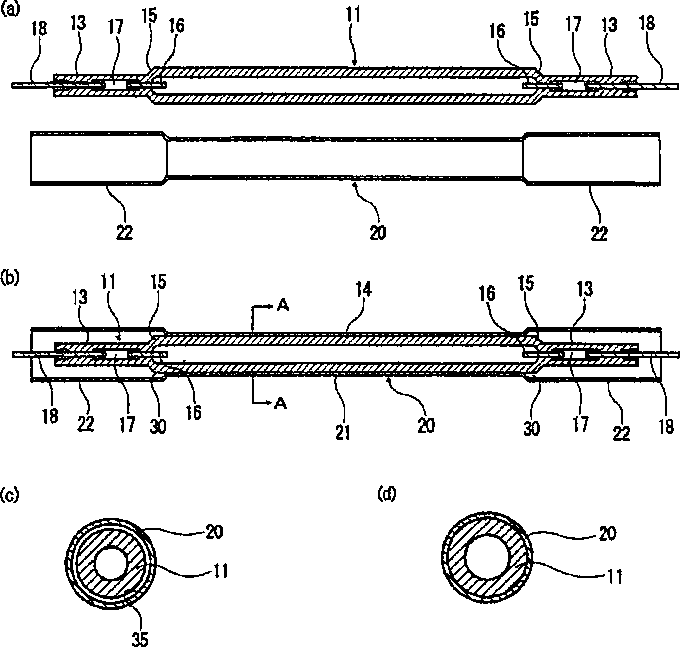
[0068] The high-pressure discharge lamp related to the second embodiment uses, for example, a straight tube whose inner diameter is uniform in the axial direction as the outer tube, and uses a rod-like material whose diameter is smaller than that of the central part located around the electrode and is located around the electrode. A gap extending over the entire circumference is formed between at least the outer peripheral surface of the supercooling preventing portion of the discharge tube and the inner peripheral surface of the outer tube. Hereinafter, the structure of the high-pressure discharge lamp concerning this 2nd Embodiment is demonstrated concretely.

[0069] Figure 4 It is an explanatory cross-sectional view showing an outline of the configuration of an example of the high-pressure discharge lamp according to the second embodiment of the present invention. Figure 5 yes means Figure 4 An enlarged sectional view of the main part of the high pressure discharge la...


PUM


Abstract

The invention provides a high-pressure discharge lamp which can obtain stable output practically for a long time, a manufacturing method which can practically obtain the high-pressure discharge lamp and a light irradiation device which can practically execute the expected light irradiation treatment. The high-pressure discharge lamp is of a dual-pipe structure which consists of a discharge tube and an external tube, and is characterized in that a pair of electrodes are relatively arranged inside the rod-shaped internal tube with two sealed ends and the rod-shaped internal tube is encapsulated by at least mercury; in the interior of the external tube, at least part of the external circumferential surface of the discharge tube is contacted with or hermetically connected with the external circumferential surface of the external tube; furthermore, a clearance extending in the whole circle is formed between the external circumferential surface of the discharge tube at least arranged at the circumference of the electrodes and the internal circumferential surface of the external tube. The high-pressure discharge lamp can be obtained by expanding the discharge tube by heating to lead the discharge tube and the external tube to be hermetically connected under a state that the external tube is internally inserted with the discharge tube. The light irradiation device is provided with the high-pressure discharge lamp.

Description

technical field [0001] The present invention relates to a high-pressure discharge lamp, a manufacturing method thereof, and a light irradiation device provided with the high-pressure discharge lamp. Background technique [0002] Currently, ultraviolet irradiation devices are used for hardening resins such as adhesives and exposure treatments of printed circuit boards, and for example, high-pressure discharge lamps are used as ultraviolet light sources of the ultraviolet irradiation devices. [0003] Various types of high-pressure discharge lamps have been proposed so far, for example, in Patent Document 1, such as Figure 10 As shown, the following capillary-type high-pressure mercury lamp 80 is disclosed. It is configured such that a pair of electrodes 83 are provided opposite to each other inside a glass tube portion 81 closed at both ends, mercury is sealed, and a lead terminal 84 with electrodes 83 at the tip is airtight. permanently penetrates the sealing portion 82, pr...

Claims


Application Information

Patent Timeline
Patent Type & Authority Applications(China)
IPC IPC(8): H01J61/34H01J61/36H01J9/24H01J61/52
Inventor 森和之大久保启介田川幸治
Owner USHIO DENKI KK
Why Eureka
Try Eureka