
Thread feeder

A technology of yarn feeder and yarn feeding wheel, which is applied in textiles and papermaking, weft knitting, knitting, etc. It can solve the problems of function damage, function loss, unpleasantness, etc., and achieve the effect of improving visibility

Active Publication Date: 2011-07-27
MEMMINGER IRO GMBH
View PDF3 Cites 1 Cited by
  • Summary
  • Abstract
  • Description
  • Claims
  • Application Information

AI Technical Summary

Problems solved by technology

Long-term accumulation of these dusts leads to unpleasant situations and even damage or loss of function

Method used

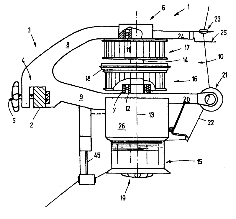
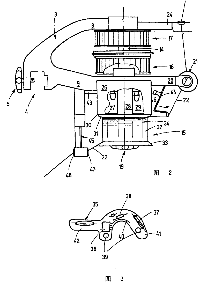
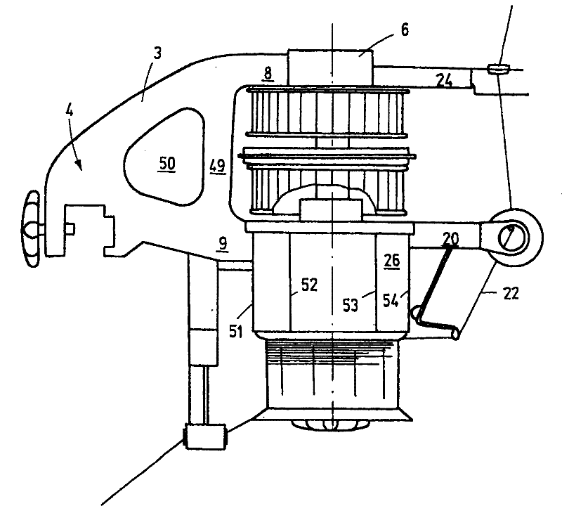

Image

  • Thread feeder
  • Thread feeder
  • Thread feeder

Examples


Embodiment Construction

[0027] in figure 1 The yarn feeder 1 is illustrated in FIG. 1, which is used to feed yarn to a knitting machine, such as a circular knitting machine. To this end, a large number of such yarn feeders are assembled on the ring 2, which is arranged horizontally on the circular knitting machine. The yarn feeder 1 has a holder 3, and the holder 3 has a clamp 4 in order to be fixed to the machine ring 2. The bracket 4 is, for example, a metal part, such as an aluminum die-cast part, a zinc die-cast part, or a plastic injection part or a plastic die-cast part. The clamp 4 has a downwardly open opening for accommodating the ring and a fastening bolt 5 in order to clamp the ring 4 in the opening. The bracket 3 extends from the clamp 4 to the first upper bearing device 6 and the second lower bearing device 7. To this end, the bracket can be as figure 1 There are, for example, two straight or arched arms 8, 9 which define a gap 10 between them.

[0028] Such as figure 1 As shown, bearing...


PUM


Abstract

The invention relates to a thread feeder that has a support (3), in which the bearing units (6, 7) are connected by a clamp (4). At least one belt pulley (16) for driving a vertical shaft (14) that is mounted in the bearing units (6, 7) is provided between said bearing units (6, 7), the lower end of said pulley being equipped with a thread delivery wheel. A housing (26), which is held by the support (3) and is designed to accommodate an electric or electronic circuit, is provided between the lower belt pulley (16) and the thread delivery wheel (15). The housing is situated in a lint-protectedregion and can thus have a relatively large volume.

Description

Technical field [0001] The present invention relates to a yarn feeder for textile machines, especially for knitting machines such as circular knitting machines, flat knitting machines and the like. Background technique [0002] Such yarn feeders are generally used to controlly feed yarn to a single loop-forming position of a knitting machine, such as a circular knitting machine. One such yarn feeder is described, for example, in the document EP 0 333 482 A1. The yarn feeder has a bracket constituted as a housing, and the bracket is provided with a fastening clip at one end for fixing the yarn feeder on the knitting machine. To this end, the knitting machine is also provided with an annular support called a machine ring, on which many basically the same yarn feeders are placed, and these yarn feeders extend radially from the support. The support of the yarn feeder has a lower arm and an upper arm, and a gap is defined between the upper and lower arms. Like the upper arm, the lo...

Claims


Application Information

Patent Timeline
Patent Type & Authority Patents(China)
IPC IPC(8): D04B15/48
CPCD04B35/14D04B15/48
Inventor M・克莱因多普R・考夫曼M・米克斯纳
Owner MEMMINGER IRO GMBH
Learn More