Drive unit for entrance and exit systems

一种驱动装置、设备的技术,应用在门装置、机械设备、运输和包装等方向,能够解决难手动移动等问题,达到结构简单的效果

Inactive Publication Date: 2009-09-16
GEBR BODE GMBH & CO KG
View PDF5 Cites 0 Cited by
  • Summary
  • Abstract
  • Description
  • Claims
  • Application Information

AI Technical Summary

Problems solved by technology

[0002] The problem caused by this type of device is that in an emergency it must be possible to manually open the passenger access door or to manually place the telescoping ladder or boarding gangway in a certain position, while the drive has a height due to the high reduction ratio of the gears Self-locking phenomenon so that it is extremely difficult to achieve manual movement, so it is difficult to do this

Method used


Image

  • Drive unit for entrance and exit systems
  • Drive unit for entrance and exit systems
  • Drive unit for entrance and exit systems

Examples


Embodiment Construction

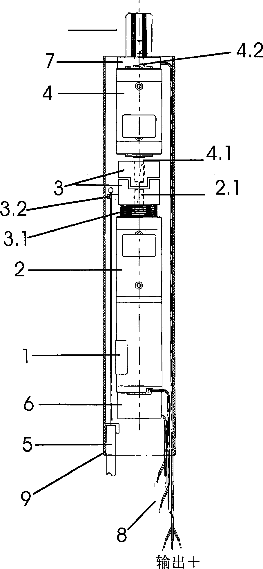
[0019] figure 1 Shows a drive configured as a compact drive train, for example a passenger access door, in a slender tubular housing, in axial succession a drive motor 1, a first reduction gear 2, an energizable clutch 3 and a second reduction gear gear 4. The driven part of the drive motor 1 is thus connected to the input part of the first reduction gear 2 , the output part 2 . 1 of the first reduction gear 2 is connected to the input part 4 . Clutch 3 cooperates under the effect of compression spring 3.1. The clutch part has an actuating plate 3.2 for disengagement, which is connected to the emergency unlocking device in a manner not shown in the figure by means of a Bowden cable 5; Clutch 3 overcomes the active force of spring 3.1 and disengages.

[0020] An actually known electromagnetic releasable brake 6 is provided on the electric motor 1 , which engages under the action of a spring and is not shown in detail here.

[0021] Furthermore, a device 7 is arranged on the...


PUM


Abstract

A drive apparatus for boarding and unboarding devices, in particular for passenger doors, boarding ramps, retractable steps and the like on public transport vehicles having an electric drive motor the driven element of which is connected to the input element of a first reduction gear the output element of which is coupled to the actuation devices for the boarding and unboarding devices where the drive apparatus is constructed as a compact drive where the electric drive motor, the first reduction gear and a second reduction gears as well as an energizable clutch are disposed axially behind each other inside a tubular housing between the first reduction gear and the second reduction gear.

Description

technical field [0001] The invention relates to a drive device for boarding and disembarking equipment, in particular for passenger access doors, boarding gangways, telescopic steps, etc., on public transport equipment with a drive motor, the driven part of which Connected to the input part of the first reduction gear, the output part of which is coupled to the actuating device of the embarkation and disembarkation device. Such drives are known per se. Background technique [0002] The problem caused by this type of device is that in an emergency it must be possible to manually open the passenger access door or to manually place the telescoping ladder or boarding gangway in a certain position, while the drive has a height due to the high reduction ratio of the gears This is difficult to do because of the self-locking phenomenon that makes manual movement extremely difficult. Contents of the invention [0003] The object of the present invention is to construct a drive wi...

Claims


Application Information

Patent Timeline
Patent Type & Authority Applications(China)
IPC IPC(8): E05F15/10
CPCE05Y2201/462E05F15/10E05Y2201/216E05Y2201/21E05Y2201/246E05Y2201/244E05Y2900/51E05Y2201/72E05Y2201/26E05F15/127E05Y2800/11B61D19/023E05F15/121E05Y2800/262E05Y2800/25E05Y2800/264E05Y2201/266E05F15/603E05F15/614E05F15/63Y10T74/19614Y10T74/2014
Inventor D·穆勒
Owner GEBR BODE GMBH & CO KG
Why Eureka
Try Eureka