Turbine blade

A technology for turbine blades and blades, applied in the directions of blade support elements, engine elements, machines/engines, etc., can solve problems such as jeopardizing operational reliability, cracks in the heat shield, and reducing the protection effect of hot exhaust gas.

A technology for turbine blades and blades, applied in the directions of blade support elements, engine elements, machines/engines, etc., can solve problems such as jeopardizing operational reliability, cracks in the heat shield, and reducing the protection effect of hot exhaust gas.

CN101535601AInactive Publication Date: 2009-09-16SIEMENS AG

Image

  • Turbine blade
  • Turbine blade
  • Turbine blade

Examples


Embodiment Construction

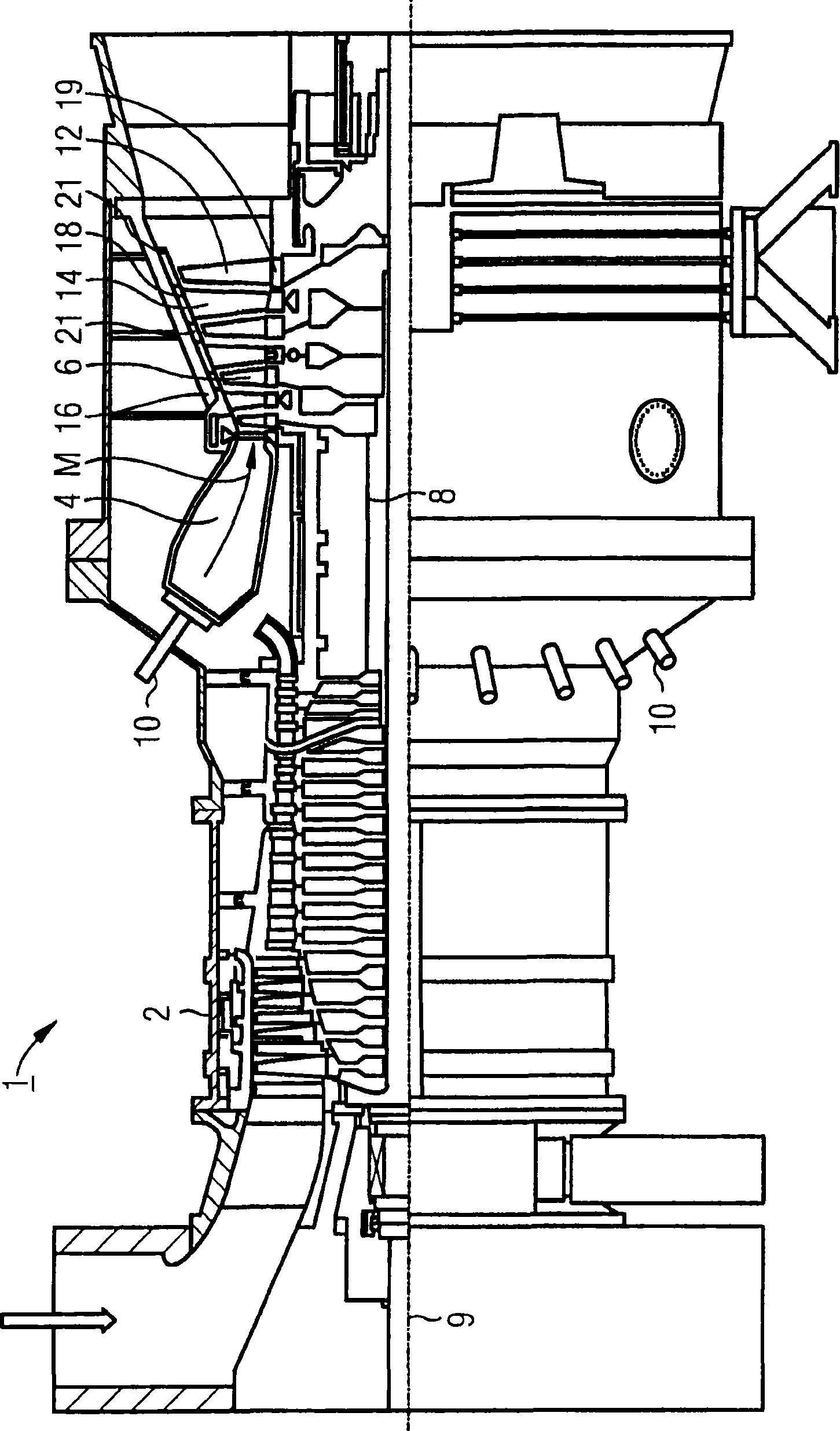
[0033] according to figure 1 The gas turbine 1 has a compressor 2 for the combustion air, a combustion chamber 4 and a turbine unit 6 for driving the compressor 2 and a generator or work machine (not shown). Furthermore, the turbine unit 6 and the compressor 2 are arranged on a common turbine shaft 8 , also referred to as the turbine rotor, to which the generator or power generator is also connected and which surrounds its central axis. 9 is rotatably supported. The combustion chamber 4 , which is designed in the manner of an annular combustion chamber, is equipped with a number of burners 10 for burning liquid or gaseous fuel.

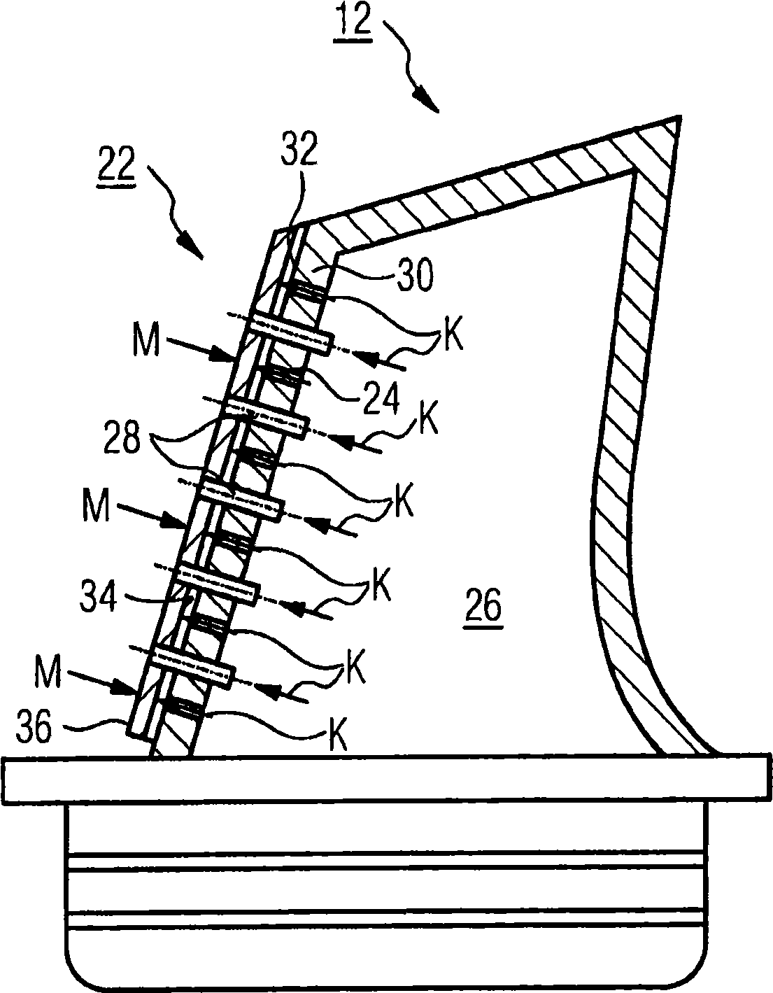
[0034] The turbine unit 6 has a number of rotatable rotor blades 12 connected to the turbine shaft 8 . The rotor blades 12 are arranged annularly on the turbine shaft 8 and thus form a number of rotor blade groups. Furthermore, the turbine unit 6 comprises a number of fixed guide vanes 14 which are likewise fastened annularly to an inner cylinder 1...


PUM


Abstract

A turbine blade (12, 14), having a plurality of auxiliary cooling channels (24) which branch off from a main cooling channel (26) which is formed within a blade basic body (30), which auxiliary cooling channels (24) open into outlet openings in the leading edge region of the blade basic body (30), is to be of particularly temperature-resistant design with respect to the working medium (M) of the turbine with a high degree of efficiency for reliable and safe operation. To this end, according to the invention, a heat shield element (22) is attached to the blade basic body (30) in the leading edge region at a predefined spacing, wherein the heat shield element (22) has a number of outlet channels (28) which are arranged behind one another in the longitudinal direction and extend from the main cooling channel (26) to the outer wall face (36) of the heat shield element (22).

Description

technical field [0001] The invention relates to a turbine blade according to the preamble of claim 1 . Background technique [0002] Fluid machines, especially gas turbines, are used in many fields to drive electrical generators or work machines. Gas turbines generally have a rotatably mounted rotor surrounded by a stationary housing. The stationary component of the gas turbine is also generally referred to as the stator. The energy content of the fuel is used here to generate the rotational movement of the rotor part. For this purpose, fuel is combusted in a fuel chamber in which air compressed by an air compressor is supplied. The working medium at high pressure and temperature produced in the combustion chamber by the combustion of the fuel is conveyed here via a turbine unit arranged downstream of the combustion chamber, in which the working medium expands while performing work. [0003] To generate the rotational movement of the rotor part, a number of rotor blades,...

Claims


Application Information

Patent Timeline
16 Sep 2009
Publication
CN101535601A
IPC
F01D5/18
CPC
F01D5/186
Inventors
F·阿马德