Multifunctional smart embroidery machine head of computerized embroidery machine

An embroidery machine and multi-functional technology, applied in the field of embroidery machine heads, can solve the problems of easy wear, low service life, high noise, etc., and achieve the effects of convenient installation and use, reduction of installation quantity, and long service life.

Inactive Publication Date: 2009-09-23
永嘉县德宝机械有限公司
View PDF0 Cites 10 Cited by
  • Summary
  • Abstract
  • Description
  • Claims
  • Application Information

AI Technical Summary

Problems solved by technology

However, this kind of tape embroidery machine head should be installed next to the original embroidery machine head, and it needs to change the installation position of the original embroidery machine head to work with the original embroidery machine head, which takes up a large installation space. Therefore, after using the tape embroidery head, the number of embroidery heads will be greatly reduced, and the production efficiency of the computerized embroidery machine will be reduced.
Moreover, the tape embroidery machine head adopts multiple sets of gear transmission mechanism, which is noisy, easy to wear and has low service life during operation.

Method used


Image

  • Multifunctional smart embroidery machine head of computerized embroidery machine
  • Multifunctional smart embroidery machine head of computerized embroidery machine

Examples


Embodiment Construction

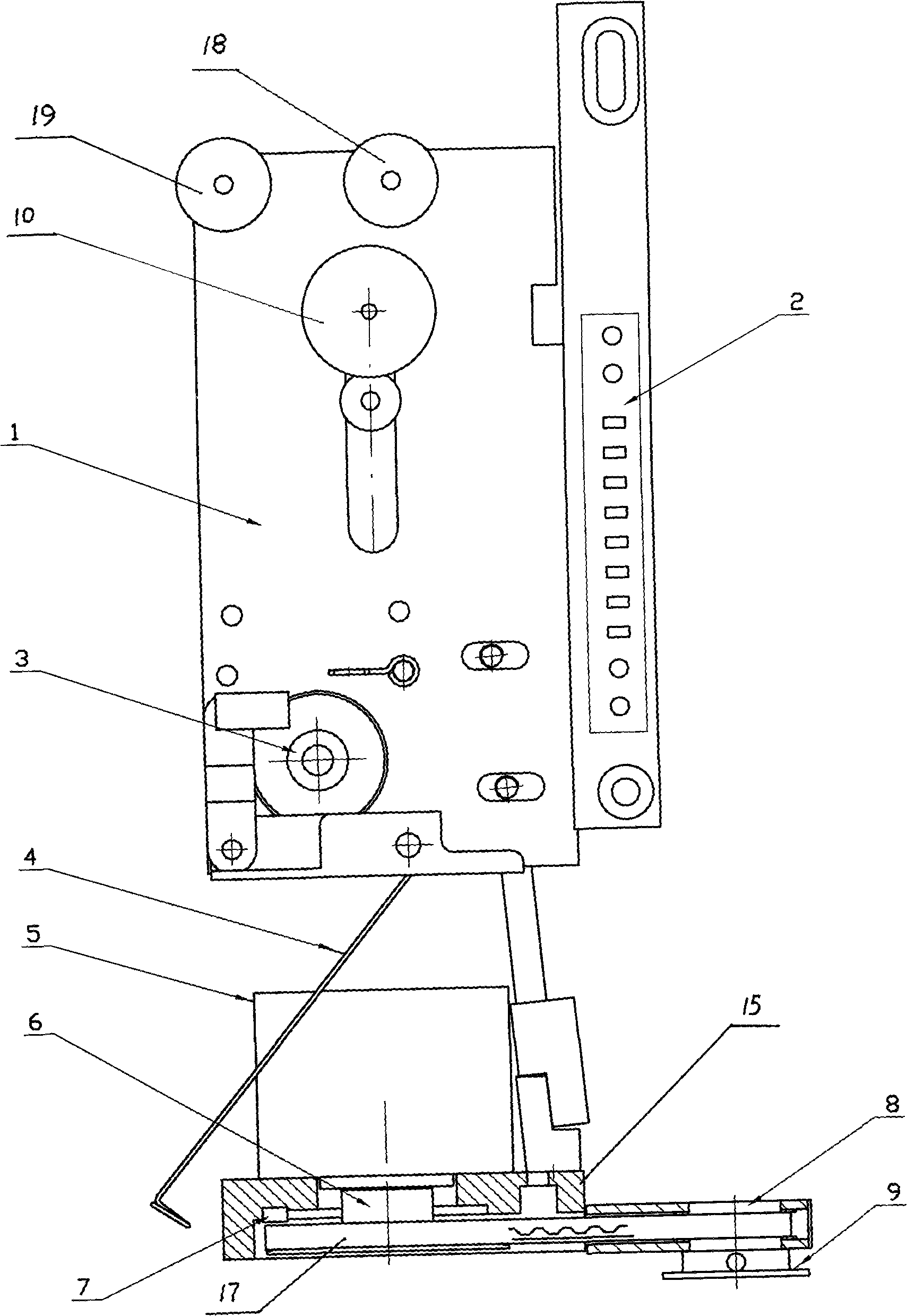
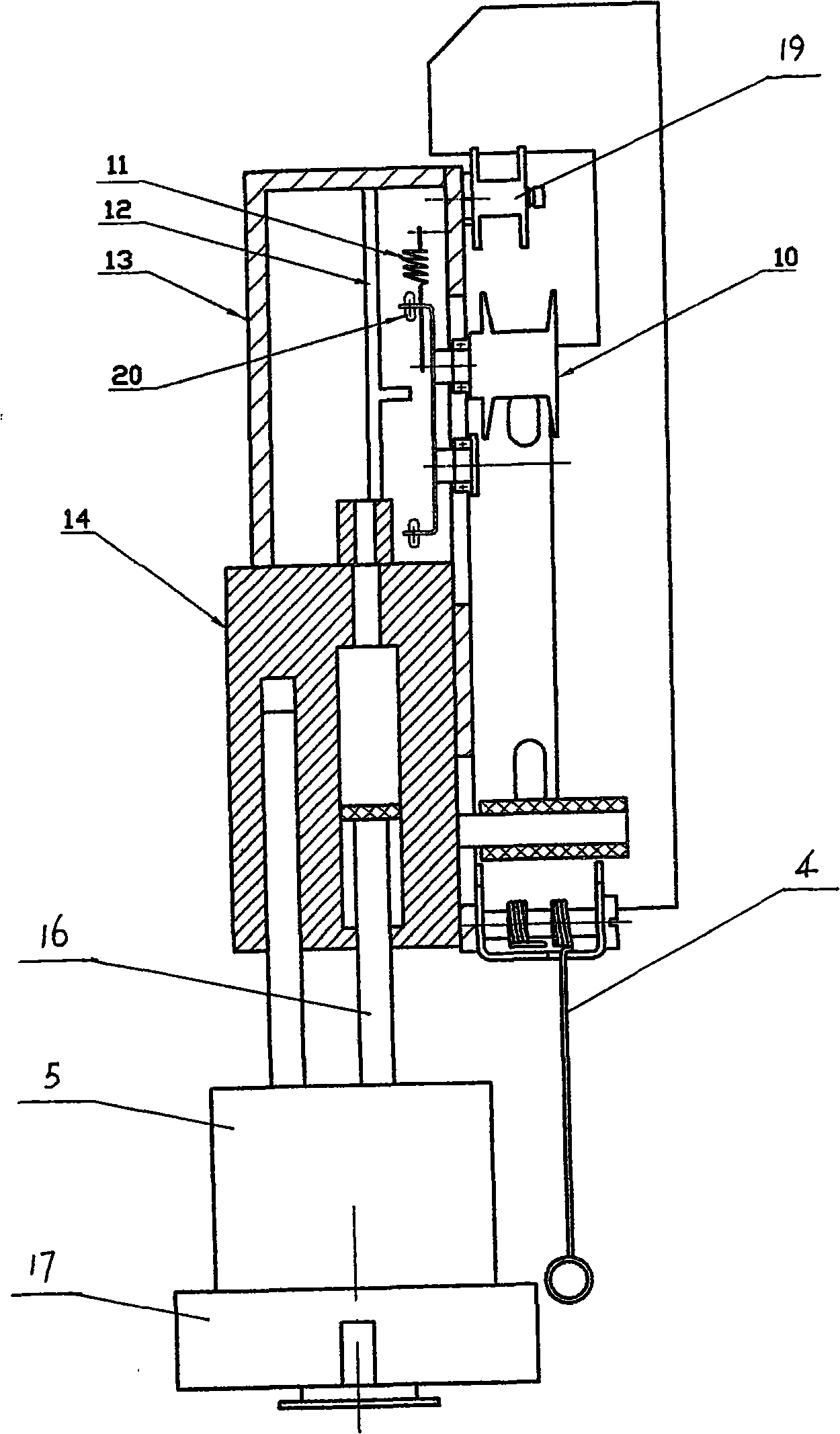
[0010] Such as figure 1 , figure 2 The multifunctional intelligent embroidery head of the computerized embroidery machine shown includes a support body 1, a control circuit board 12, an instruction operation circuit board 2, a feeding motor 5 and a transmission cylinder 14, a control circuit board 12, an instruction operation circuit board 2 and a transmission cylinder 14 is fixedly installed on the bracket body 1, the feeding motor 5 is fixedly connected with the lower end of the piston rod 16 of the transmission cylinder 14 through the mounting seat 15, and the output shaft of the feeding motor 5 is fixedly connected with the driving pulley 6, and the driving pulley 6 is connected to the line through the transmission belt 17. The driven pulley 8 on the material guide port 9 is connected, and the side of the thread guide port 9 is shaped on a thread material hole, and the center is shaped on an inner through hole, and the needle bar of the flat embroidery head of the compute...


PUM


Abstract

The invention relates to a multifunctional smart embroidery machine head of a computerized embroidery machine, comprising a support body, a control circuit board, an instruction operation circuit board, a feeding motor and a drive cylinder, and a driving belt wheel on the feeding motor is connected with a driven belt wheel on a thread guide port through a drive belt. The multifunctional smart embroidery machine head is mainly provided with an inner through hole in the thread guide port, the inner through hole is sleeved on the outside of a needle bar of a flat embroidery machine head; a tension motor, a mobile guide wheel, a tension swing spring, a first fixed guide wheel and a second fixed guide wheel are arranged on the support body; a stroke control switch is arranged between the driving belt wheel and a mounting base, and the stroke control switch is connected in a forward and backward rotation control circuit of the feeding motor. The multifunctional smart embroidery machine head does not need to change the mounting position of the original flat embroidery machine head, does not reduce the mounting number of the flat embroidery machine head and has the advantages of convenient installation and use, high production efficiency, low noise, long service life and so on. The multifunctional smart embroidery machine head is applicable to the computerized embroidery machines of flat embroidery, belt embroidery, rope embroidery, bead embroidery and coil embroidery.

Description

technical field [0001] The invention relates to an embroidery head of a computerized embroidery machine, in particular to a multifunctional embroidery head of a computerized embroidery machine used for tapes, ropes, beads and tubes. Background technique [0002] Computer embroidery machine technology develops along with the development of embroidery patterns. Through the control of computer programs, it realizes the embroidery function of various plane patterns, which has been widely popularized and applied, and one machine is arranged with multiple heads to achieve high production efficiency. . However, with the development of people's demand for three-dimensional pattern embroidery, new requirements are put forward for computer embroidery machine technology. For example, the "tape embroidery machine head" with the Chinese patent No. ZL2007201119808 adopts an independent small motor and a gear transmission mechanism connected to it, and the small motor drives the tape feed...

Claims


Application Information

Patent Timeline
Patent Type & Authority Applications(China)
IPC IPC(8): D05C5/00D05C7/00D05C13/00
Inventor 庄军周仁俊
Owner 永嘉县德宝机械有限公司
Why Eureka
Try Eureka