
Water-trap type water-saving squatting pan

A technology of water-saving squatting toilets and squatting toilets, which is applied in flushing toilets, water supply devices, buildings, etc., and can solve problems such as low momentum, blocked water outlets, and large water consumption

Active Publication Date: 2011-06-15
BEIJING KANGZHIWEI SCI & TECH
View PDF0 Cites 0 Cited by
  • Summary
  • Abstract
  • Description
  • Claims
  • Application Information

AI Technical Summary

Problems solved by technology

[0002] Squatting toilets are widely used in public places, and have the characteristics of high frequency of use and large water consumption; but they also generally have problems of poor flushing effect, large water consumption, and waste of water resources
Through the long-term observation of the inventor, it is found that the problem of high water consumption and unclean flushing is mainly due to: 1. Because the dirt floats up, it cannot be flushed during normal flushing, and it must be flushed twice to cause water waste
2. Because the outlet of the storage bay is blocked, it must be flushed many times, resulting in waste of water
3. If the momentum is small, more water must be used to rinse, resulting in a waste of water with a large amount of water each time

Method used


Image

  • Water-trap type water-saving squatting pan
  • Water-trap type water-saving squatting pan
  • Water-trap type water-saving squatting pan

Examples


Embodiment Construction

[0011] Below in conjunction with the accompanying drawings and specific examples for further description

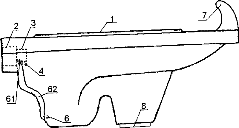
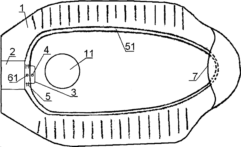
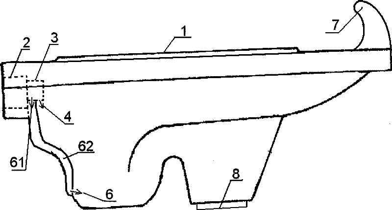
[0012] Such as Figure 1-2 As shown, the water-saving bay type water-saving squatting pan of the present invention is that the water inlet 2 is shaped on the rear end of the squatting pan 1, the front of the water inlet 2 is a flushing nozzle 3, and the bottom of the flushing nozzle 3 front is shaped on a direct-shooting water storage bay 11. Jet flushing hole 4, flushing nozzle 3 both sides respectively have a lateral flushing hole 5 shooting at the flushing tank 51 between the squatting pan side wall and the flushing tank baffle on both sides of the squatting pan, the flushing nozzle 3 is spraying and flushing. Hole 4 rear side is shaped on flushing object water outlet 61, is shaped on the interlayer type waterway 62 that communicates flushing object water outlet 61 on the rear wall between storage bay 11 and flushing nozzle 3, is shaped on the front wall of the lower e...


PUM


Abstract

The invention relates to a water-trap type water-saving squatting pan. For solving the problems of the prior squatting pan such as poor flushing effect and water waste, the water-trap type water-saving squatting pan adopts a technical proposal that: the rear end of the squatting pan is provided with a water inlet; a flushing nozzle is arranged in front of the water inlet; an injection flushing hole is arranged under the front part of the flushing nozzle; each of the two sides of the flushing nozzle is provided with a lateral flushing hole injecting toward a flushing tank which is positioned on two sides of the squatting pan and between the side wall of the squatting pan and the flushing tank baffle; the flushing nozzle is provided with a flushing material water outlet at a position behindthe injection flushing holes; a rear wall between a water trap and the flushing nozzle is provided with a sandwich type water channel communicated with the flushing material water outlet; and a frontwall of the lower end of the sandwich type water channel is provided with a flushing material flushing hole pointing to a water trap water outlet. The injection flushing hole is a material pressing injection flushing hole directly injecting toward the water trap. The water-trap type water-saving squatting pan can prevent sewage from floating up even with a small amount of water and avoid secondary flushing when the squatting pan is not well flushing through material pressing water flows toward the water trap, can improve flushing speed, prevent blockage and flush away sewage even with a smallamount of water through the flushing material flushing hole pointing to the water trap water outlet, and has the advantages of obviously improved instantaneous flushing flow speed, good flushing effect and obvious water-saving effect.

Description

technical field [0001] The invention relates to a water-flushing toilet device, in particular to a water-saving bay-type squatting toilet. Background technique [0002] Squatting toilets are widely used in public places, and have the characteristics of high frequency of use and large water consumption; but they also generally have the problems of poor flushing effect, large water consumption, and waste of water resources. Find through long-term observation of the inventor, water consumption is many, and the problem of not flushing clean is mainly because: 1, because dirt floats up, can't flush completely during normal flushing, must flush twice and cause water waste. 2. Because the water outlet of the storage bay is blocked, it must be flushed many times, resulting in waste of water. 3. If the momentum is small, more water must be used to flush, resulting in a waste of water with a large amount of water each time. Contents of the invention [0003] The object of the pres...

Claims


Application Information

Patent Timeline
Patent Type & Authority Patents(China)
IPC IPC(8): E03D11/13
Inventor 陈向前郭洪喜
Owner BEIJING KANGZHIWEI SCI & TECH
Learn More