Solid state light source device

A technology of solid-state light sources and light guides, which is applied in the direction of light sources, point light sources, lighting devices, etc., can solve the problems of limited luminous brightness and difficulty in achieving efficiency, and achieve the effect of increasing the effective luminous area

Inactive Publication Date: 2009-09-23
曹嘉灿
View PDF0 Cites 2 Cited by
  • Summary
  • Abstract
  • Description
  • Claims
  • Application Information

AI Technical Summary

Problems solved by technology

[0002] As a new type of high-brightness, long-life light source, solid-state light-emitting devices such as high-power LEDs (including OLEDs) have achieved considerable development in lighting and other application fields. The lack of projection light sources, but to apply LED and other solid-state light-emitting devices to projection systems, it is necessary to require the constituted light source to be an ideal point light source, but the illuminant of each LED is a semiconductor chip with a certain light-emitting area. It is essentially a small surface light source, and because the luminance of a single LED chip is limited, in order to achieve a large enough luminous flux, it is usually necessary to arrange multiple LED chips in an array, or use a larger size LED surface illuminant. While the luminous flux is multiplied, the luminous area of ​​the light source is also multiplied accordingly. When the luminous area of ​​the light source is larger, the imaging light efficiency of the corresponding projection imaging optical system is lower. The output flux (luminous brightness) is difficult to work hard, which is the main technical obstacle to apply solid light sources such as high-power LEDs to projection systems

Method used


Image

  • Solid state light source device
  • Solid state light source device
  • Solid state light source device

Examples


Embodiment Construction

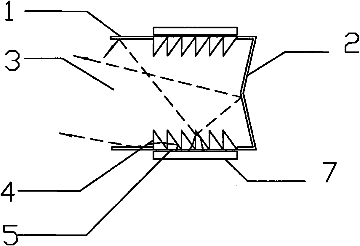
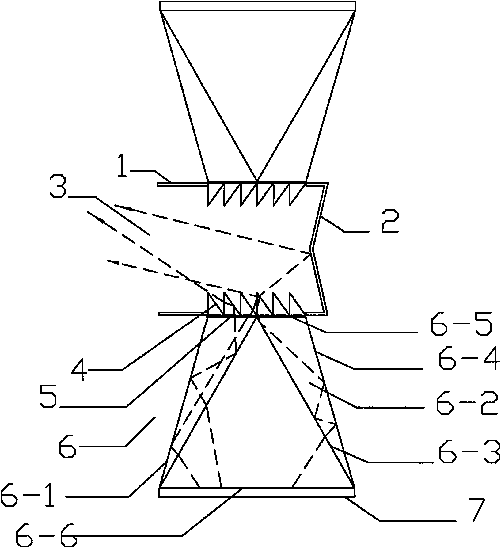
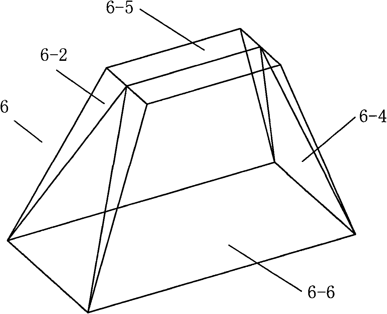
[0025] In the present invention, a prism-shaped light guide 6 with a light incident area larger than the light-emitting area is provided between the light entrance 5 of the optical member 1 and the surface light guide 7. After the light emitted by the surface luminous body 7 passes through the prism-shaped light guide 6 , and then refracted or totally reflected by the light guide prism 4, reflected by the reflector or directly emitted from the light outlet 3 of the optical member 1, the effective light emission of the surface luminous body 7 is increased without changing the size of the optical member 1 and the light inlet 5 Area, or maintain the same effective light-emitting area of ​​the surface luminous body, and can reduce the light entrance area of ​​the solid-state light source device, that is, reduce the volume of the hexahedral optical component and the light exit area, making it closer to the ideal point light source.

[0026] Such as figure 2 As shown, a solid-state...


PUM


Abstract

The invention relates to a solid state light source device, which comprises a hollow optical component which has a cavity containing air, vacuum or other light-transmitting mediums. The optical component provided with a light outlet is polyhedron-shaped and is provided with at least one light inlet, at least one light guide prism corresponding to the light inlet, and a surface illuminator corresponding to the bottom surface of the light guide prism. Reflection parts are arranged inside the optical component or inside and outside the optical component. A frustum-shaped light guide part of which the light incident area is larger than the light emergent area is arranged between the light inlet of the optical component and the surface illuminator; and after passing through the frustum-shaped light guide part, the light emitted by the surface illuminator is refracted or completely reflected by the light guide prism, and then is reflected by the reflection parts or directly emitted via the light outlet. As the frustum-shaped light guide part of which the light incident area is larger than the light emergent area is arranged between the light inlet of the optical component and the surface illuminator, the solid state light source device can enlarge the effective light-emitting area of the surface illuminator without changing the sizes of the optical component and the light inlet.

Description

technical field [0001] The present invention relates to light source devices, and more particularly to an improved solid state light source device. Background technique [0002] As a new type of high-brightness, long-life light source, solid-state light-emitting devices such as high-power LEDs (including OLEDs) have achieved considerable development in lighting and other application fields. The lack of projection light sources, but to apply LED and other solid-state light-emitting devices to projection systems, it is necessary to require the constituted light source to be an ideal point light source, but the illuminant of each LED is a semiconductor chip with a certain light-emitting area. It is essentially a small surface light source, and because the luminance of a single LED chip is limited, in order to achieve a large enough luminous flux, it is usually necessary to arrange multiple LED chips in an array, or use a larger size LED surface illuminant. While the luminous f...

Claims


Application Information

Patent Timeline
Patent Type & Authority Applications(China)
IPC IPC(8): F21V13/00F21V8/00F21V5/02F21V7/00F21Y101/02F21Y115/10
Inventor 曹嘉灿
Owner 曹嘉灿
Why Eureka
Try Eureka