Virtual particle plasma generating device

A power generation device and plasma technology, applied in electromechanical devices, nuclear power generation, electrical components, etc., can solve problems such as structural instability, insufficient ToKamak container energy level, and inability to control the trajectory of neutral particles, so as to eliminate fuel pollution and structure Simple, well-designed effects

Inactive Publication Date: 2009-09-23
周先德
View PDF0 Cites 2 Cited by
  • Summary
  • Abstract
  • Description
  • Claims
  • Application Information

AI Technical Summary

Problems solved by technology

[0004] However, the ToKamak device has the following defects and deficiencies in actual use: the first, the ToKamak tire type structure is unstable, because there are a large amount of neutral particles (this is a necessary condition for power generation) in the ToKamak, and although the magnetic field can control the electrification The trajectory of the particle, but the trajectory of the neutral particle cannot be controlled
Second, the energy level of the ToKamak container is insufficient, and the sufficient condition for continuous power generation is to have a strong nuclear force (≥10 3 Gev), it must be possible to convert the molecular atomic fuel into Q (quark)-G (gluon) or F (fermion)-B (boson) fuel through high energy, and the energy level of the electromagnetic force of the ToKamak container is the same as The strong nuclear force differs by 10 2 Heavyweight, this is beyond ToKamak's reach

Method used


Image

  • Virtual particle plasma generating device
  • Virtual particle plasma generating device

Examples


Embodiment 1

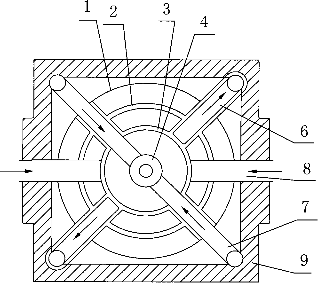
[0023] like figure 1 As shown, the present invention includes a spherical strong nuclear force containment body 1, a white hole ball 2 that is set inside the spherical strong nuclear force containment body 1 and made of electromagnetic materials, and a white hole ball 2 that is set inside the white hole ball 2 and is formed by the weak nuclear force. The wormhole ball 3 made of material, the black hole ball 4 which is set inside the wormhole ball 3 and made of strong nuclear force material, respectively extend from the outside of the spherical strong nuclear force containment body 1 to the wormhole ball 3 and the black hole ball 4 and fuel input channel 1 6 and fuel input channel 2 7 for inputting the composite fuel composed of positively charged electric material and negatively charged electric material, and extending from the outer side of the spherical strong nuclear force enclosure 1 to the wormhole ball 3 And used to input not more than 10 3 Driving energy channel 8 for ...

Embodiment 2

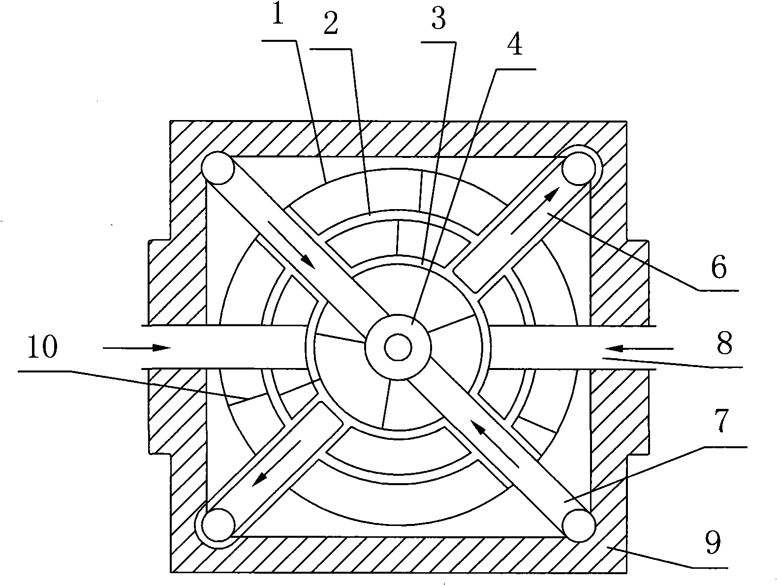
[0030] like figure 2 As shown, the difference between this embodiment and Embodiment 1 is that the white hole ball 2 , the wormhole ball 3 and the black hole ball 4 are not fixed on the outer walls of the first fuel input channel 6 and the second fuel input channel 7 . Between the spherical strong nuclear force concealment body 1 and the white hole ball 2, between the white hole ball 2 and the wormhole ball 3, and between the wormhole ball 3 and the black hole ball 4, there are no multiple fixed connecting rods 10 for fixing . In this embodiment, between the spherical strong nuclear force concealment body 1 and the white hole ball 2, between the white hole ball 2 and the wormhole ball 3, and between the wormhole ball 3 and the black hole ball 4, a plurality of fixed The connecting rod 10 is fixed. The number of the plurality of fixed connecting rods 10 is specifically three. The structures, connections and working principles of the remaining parts are the same as those in ...


PUM


Abstract

The invention discloses a virtual particle plasma generating device which comprises a spherical strong nuclear force closing body, a strong nuclear force white hole ball sleeved in the spherical strong nuclear force closing body, a weak nuclear force bug hole ball sleeved in the strong nuclear force white hole ball, a strong nuclear force black hole ball sleeved in the weak nuclear force bug hole ball, a fuel input channel used for inputting composite fuel formed by positive charge electrical materials and negative charge electrical materials, and a drive energy channel used for inputting drive energy with 10<3>Gev-10<5>Gev. The diameter proportion of the spherical strong nuclear force closing body, the strong nuclear force white hole ball, the weak nuclear force bug hole ball and the strong nuclear force black hole ball is 4:3:2:1, and the centers of sphere of the four balls are the same center of sphere 0; and the black hole ball is a Q-G particle sieve ball generated by the composite fuel in the spherical strong nuclear force closing body after the annihilation reaction under the action of the drive energy. The invention has simple and reasonable structure, convenient operation and good use effect, not only can continuously stably output the highest electric power, but also is low in cost, consumes little fuel, and has the function of cleaning fuel.

Description

technical field [0001] The invention relates to a power generation device, in particular to a virtual particle plasma power generation device. Background technique [0002] ToKamak (that is, Tokamak) is a transliteration of the Russian abbreviation. The ToKamak device was proposed by Soviet scientists Sakharov and Tam in 1950. It uses a magnetic field to confine the charged particles in the plasma so that they do not escape. It is referred to as the "magnetic confinement" container (or device). The working principle of ToKamak is: using a magnetic field to constrain the orbit of charged particles in the plasma, so that the charged particles orbit around the magnetic force lines generated by the magnetic field. In actual use, artificially create an external toroidal magnetic field Bp for the ToKamak device, so that plasma charged particles do Larmor motion around the magnetic field lines, and there is a plasma current Ip at this time, and this current will generate a toroida...

Claims


Application Information

Patent Timeline
Patent Type & Authority Applications(China)
IPC IPC(8): G21B1/00H02K44/00
CPCY02E30/10
Inventor 周先德朱小鸣周铭周锋
Owner 周先德
Why Eureka
Try Eureka