Gas compressor

A gas compressor and compressor technology, applied in the field of gas compressors, can solve the problems of reduced volume efficiency and high refrigerant gas temperature, and achieve the effect of preventing excessive reduction and excessive oil separation

Inactive Publication Date: 2009-09-30
CALSONIC KANSEI CORP
View PDF5 Cites 9 Cited by
  • Summary
  • Abstract
  • Description
  • Claims
  • Application Information

AI Technical Summary

Problems solved by technology

Then, the amount of refrigerating machine oil mixed into the refrigerant gas sucked into the compression chamber decreases, the amount of refrigerating machine oil introduced into the compression chamber together with the refrigerant gas decreases, and the refrigerating machine oil functioning as a cooling medium decreases. The temperature of the refrigerant gas becomes higher, which results in a decrease in volumetric efficiency

Method used


Image

  • Gas compressor
  • Gas compressor
  • Gas compressor

Examples


Embodiment 1

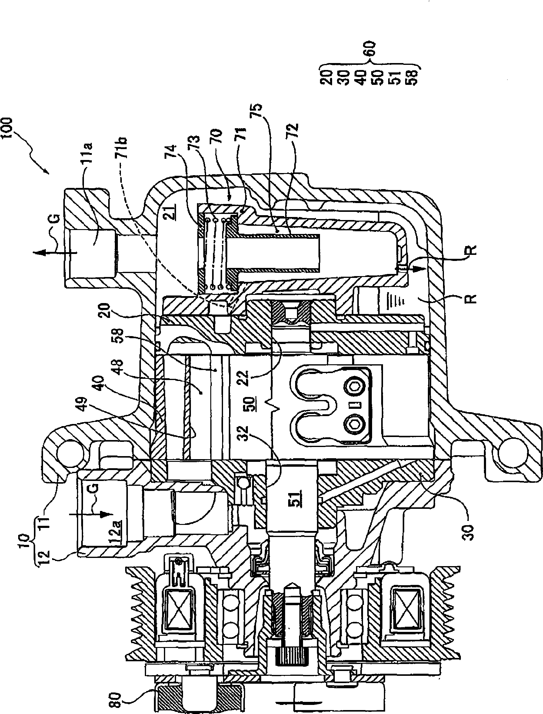
[0081] The cyclone body 70 is assembled to the rear block 20 of the compressor main body 60 and separates refrigerating machine oil R (oil component) from high-pressure refrigerant gas G discharged from the compression chamber 48 via the rear block 20 .

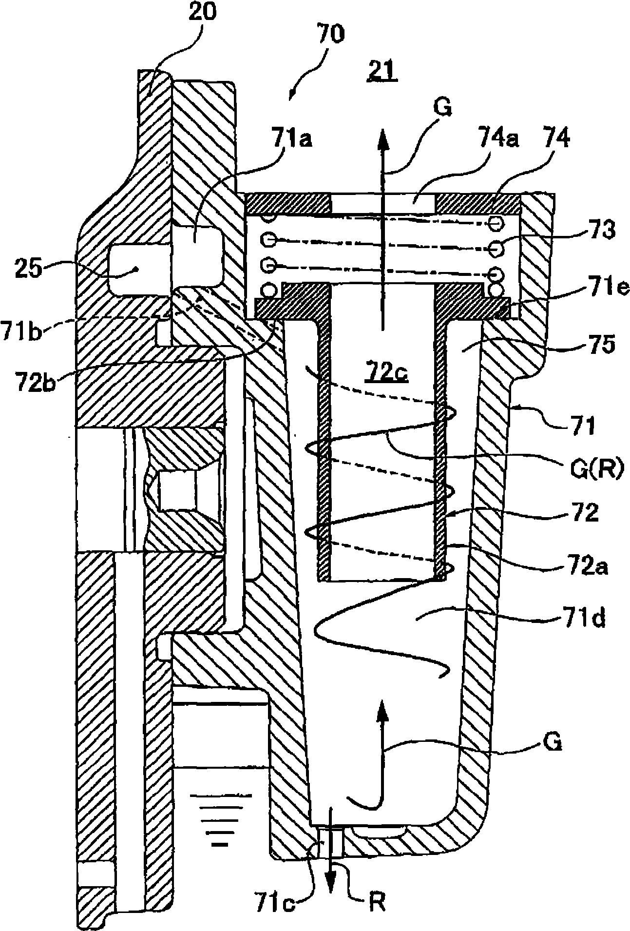
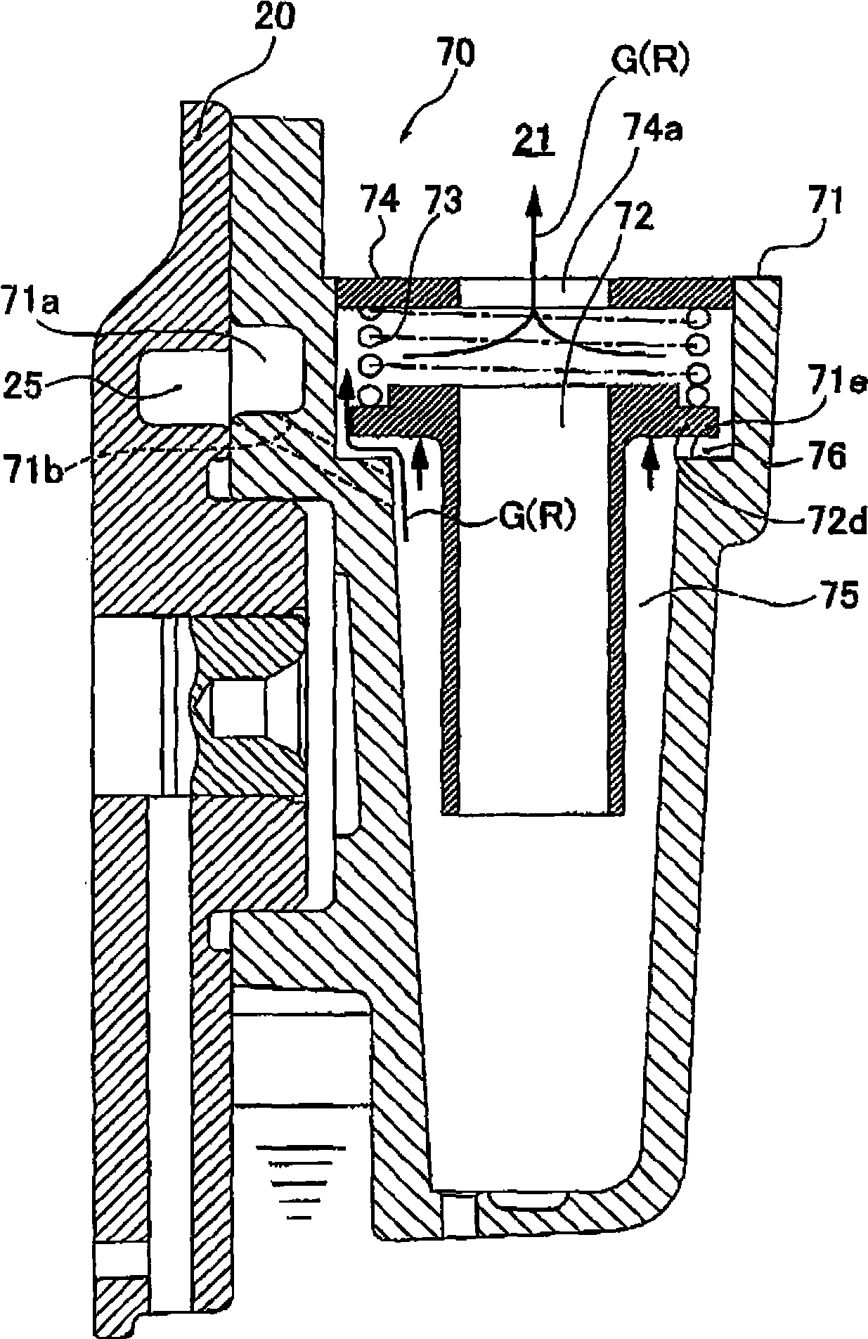
[0082] like figure 2 As shown in detail, the cyclone body 70 has:

[0083] The main body part 71 forms a substantially cylindrical space 71d with a closed lower end, and a base surface 71e is formed on the end side of the unclosed side;

[0084] The inner cylinder member 72 has a substantially cylindrical inner cylinder portion 72a having a smaller diameter than the approximately cylindrical space 71d of the main body member 71, and has an upper end connected to the inner cylinder portion 72a and capable of being connected to the main body member 71. The flange portion 72b that the base surface 71e abuts against;

[0085] The coil spring 73 is arranged in a state in which the inner cylinder portion 72a of the inner cylinde...

Embodiment 2

[0110] E.g, Figure 4B , Figure 4C With figure 2 , image 3 Equivalent Figure 4A and along Figure 4A A cross-sectional view of line A-A in, such as Figure 4B , Figure 4C As shown, a structure is considered in which the second passage 71a communicating with the main body member 71 and the pressure bypass passage 77 of the discharge chamber 21 are formed on the main body member 71, and a leaf spring valve 79 (pressure valve) is provided on the main body member 71. The leaf spring valve 79 is fixed by a fastening member 78 and opens and closes the pressure bypass passage 77 according to the internal pressure of the compressed gas passage.

[0111] Furthermore, when the internal pressure of the compressed gas passage is lower than a predetermined pressure, as in Figure 4B As shown, the leaf spring valve 79 is not deformed, maintains the state of closing the pressure bypass passage 77 , and guides the refrigerant gas G discharged from the compression chamber 48 into t...

Embodiment 3

[0118] Figure 5 It is a longitudinal sectional view showing a rotary vane compressor 100 as an embodiment of the gas compressor according to the present invention, and Fig. 6 and Fig. 7 are diagrams showing Figure 5 An enlarged view of the details of the cyclone body 70 in .

[0119] This embodiment has the same compressor main body as the above embodiment, and the only difference from the above embodiment is the cyclone body. Therefore, only the cyclone body will be described below.

[0120] The cyclone body 170 is assembled on the rear block 20 of the compressor main body 60, and separates the refrigerating machine oil R (oil component) from the high-pressure refrigerant gas G discharged from the compression chamber 48 through the rear block 20, as shown in FIG. 6 As shown in detail, it has: a main body part 171, which has a substantially cylindrical space 171e with a closed lower end; The axial direction of the space 171e is set.

[0121] A discharge hole 171c for dis...


PUM


Abstract

The invention provides a gas compressor for preventing excessive reduction of oil circulation during a high speed operation. A cyclone block (70) is configured to include a substantially cylindrical space (75) into which a compressed coolant gas (G) is introduced to separate refrigeration oil (R) from the gas (G). A pressure bypass (76) is formed in the substantially cylindrical space (75) defined by an outer cylindrical unit (71) and an inner cylindrical unit (72) to communicate with a discharge chamber (21) having lower pressure than that of the substantially cylindrical space (75). The pressure bypass (76) includes a pressure valve to open and close the pressure bypass (76) in accordance with the internal pressure of the substantially cylindrical space (75) having the pressure bypass (76). During a high speed operation of a compressor unit (60), the coolant gas (G) including unseparated refrigeration oil (R) is discharged from the pressure bypass (76).

Description

technical field [0001] The present invention relates to a gas compressor, and in particular, to an improvement of an oil separator for centrifugally separating oil from compressed gas discharged from a compressor main body. Background technique [0002] Conventionally, in an air conditioning system (hereinafter referred to as an air conditioning system), a gas compressor (compressor) that compresses gas such as refrigerant gas and circulates the gas in the air conditioning system is used. [0003] Here, a general compression mechanism includes a compressor main body that compresses and discharges gas, and an oil separator that separates oil components such as refrigerating machine oil from the compressed refrigerant gas discharged from the compressor main body. [0004] As an oil separator, for example, an oil separator as follows is known: the oil separator has: a main body member having an approximately cylindrical space whose lower end surface is closed by an end wall for...

Claims


Application Information

Patent Timeline
Patent Type & Authority Applications(China)
IPC IPC(8): F04C29/02
Inventor 饭岛博史大野浩干
Owner CALSONIC KANSEI CORP
Why Eureka
Try Eureka