Optical transmission spherical surface detector

A detection device and optical transmission technology, applied in the direction of optical devices, measuring devices, optics, etc., can solve the problems affecting the surface finish of the tested spherical surface, the difficulty of sample processing, and the damage of the tested spherical surface.

Inactive Publication Date: 2009-09-30
NANJING UNIV OF SCI & TECH
View PDF0 Cites 20 Cited by
  • Summary
  • Abstract
  • Description
  • Claims
  • Application Information

AI Technical Summary

Problems solved by technology

The problems of this traditional template detection method are: 1. Since each curvature radius value requires at least one template, and requires a convex-concave pair template with the same curvature radius, the surface shape and curvature radius of the templates are different according to grades. Quality requirements, so spherical processing manufacturers must have a large number of sample libraries, resulting in high cost of fixed asset types, and the processing of each pair of samples is also difficult; 2. The sample method measurement is to contact the sample with the spherical surface to be inspected , is a contact measurement method, which is likely to cause damage to the surface of the spherical surface to be inspected, surface defects such as scratches, and affect the surface finish of the inspected spherical surface: 3. The data of the spherical surface shape of the sample method is only described by the number of apertures. Not only the method is backward, but also the accuracy is low, and the error of the model itself cannot be deducted quantitatively

Method used


Image

  • Optical transmission spherical surface detector
  • Optical transmission spherical surface detector
  • Optical transmission spherical surface detector

Examples


Embodiment Construction

[0014] The present invention will be described in further detail below in conjunction with the accompanying drawings.

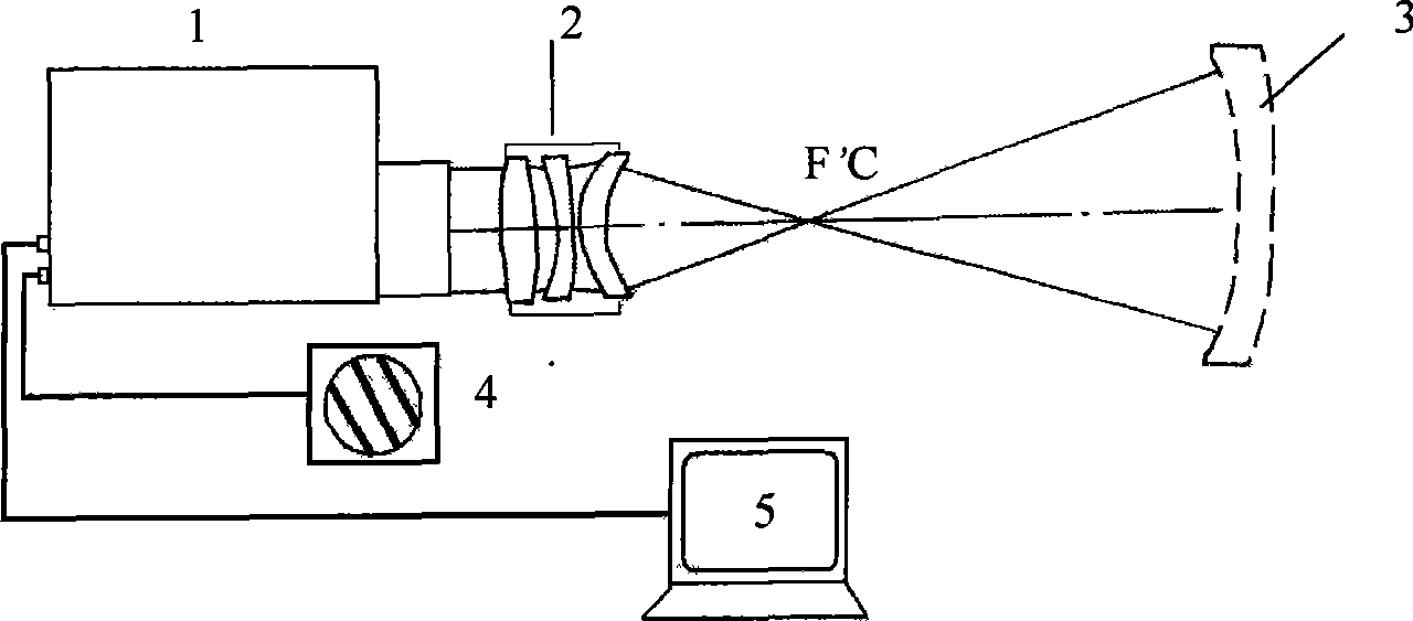
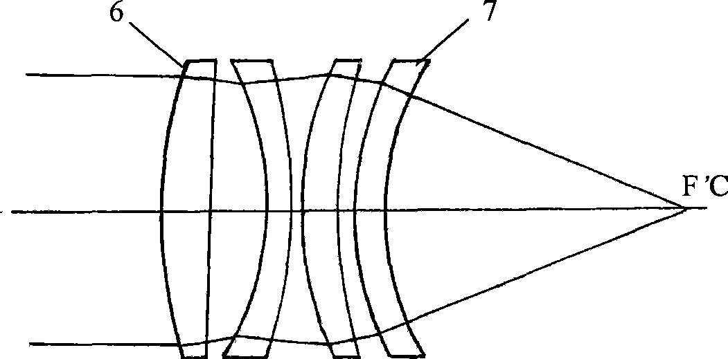
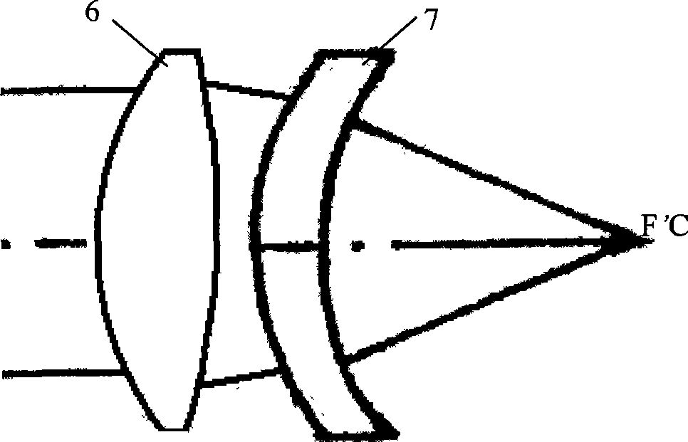
[0015] see figure 1 , according to the optical transmission spherical detection device that the present invention makes, it is made up of digital wave surface interferometer 1, transmission spherical surface apparatus 2, interferogram monitor 4 and computer 5, and digital wave surface interferometer 1 is the digital based on single interferogram processing The wavefront interferometer or the phase-shifting digital wavefront interferometer based on phase-shifting technology, the interferogram monitor 4 is used to display the interferogram reflecting the spherical surface shape to be tested, and the computer 5 is embedded with a digital image acquisition system and interferogram processing software, The transmission spherical device 2 is located on the outgoing light path of the digital wave surface interferometer 1, and it is composed of 2 to 4 optical positiv...


PUM


Abstract

The invention discloses an optical transmission spherical surface detector for inspecting the surface shape quality of lens convex-concave spherical surfaces, which is characterized by adopting a spherical surface non-contact interference method to obtain a standard spherical wave of which the curve radius changes continuously in certain range by a standard transmission spherical surface instrument consists of a group of positive lenses so as to achieve the detection of the convex-concave spherical surfaces with different curve radiuses, wherein the relative aperture detection coverage of a detected piece can reach F/0.75 to 11. The optical transmission spherical surface detector has the characteristics of multiple functions, no damage to the surface finishment of a detected spherical surface and high test precision, and overcomes the disadvantage of contact measurement of the prior spherical surface sample plate; and if the optical transmission spherical surface detector is used together with a length-measuring linear scale, a length-measuring interferometer, and the like, the curve radiuses of the spherical surfaces can be measured precisely. The optical transmission spherical surface detector can be extensively applied to the optical manufacturing industry to inspect the surface shape quality of various lens convex-concave spherical surfaces.

Description

technical field [0001] The invention relates to a Fizeau-type light interference measurement device, in particular to an optical transmission spherical surface detection device used for quality inspection of convex and concave spherical surfaces of lenses. Background technique [0002] Existing optical processing industry usually adopts the template method to test the quality of convex-concave spherical surface of the lens, that is, through different optical templates contacting the corresponding convex-concave spherical surface to be tested, and then observing different apertures due to surface shape deviation with the naked eye. The quality of the spherical surface is judged. When testing, a radius of curvature needs a pair of convex and concave samples. When the surface of the sample is in contact with the tested spherical surface, if there is an air gap between the tested spherical surface and the sample surface, equal-thickness stripes will be formed, which reflects the...

Claims


Application Information

Patent Timeline
Patent Type & Authority Applications(China)
IPC IPC(8): G01B11/24G01B11/255G01M11/02G02B3/00G02B1/10G02B1/11
Inventor 高志山朱日宏陈磊王青何勇
Owner NANJING UNIV OF SCI & TECH
Why Eureka
Try Eureka