Selected zone laser melting and rapid forming method for metal parts and apparatus thereof

A technology for selective laser melting and metal parts, applied in the field of metal parts forming and processing, it can solve the problems of poor dimensional accuracy and surface finish of metal parts, achieve good mechanical properties, prevent cracks and pores, and have a wide range of applications.

Inactive Publication Date: 2005-04-06
SOUTH CHINA UNIV OF TECH
View PDF0 Cites 64 Cited by
  • Summary
  • Abstract
  • Description
  • Claims
  • Application Information

AI Technical Summary

Problems solved by technology

However, this technique uses high-power lasers, including kilowatt-class CO 2 And Nd:YAG laser, although metallurgically bonded dense metal entities can be obtained, due to the large spot in the las...

Method used


Image

  • Selected zone laser melting and rapid forming method for metal parts and apparatus thereof
  • Selected zone laser melting and rapid forming method for metal parts and apparatus thereof
  • Selected zone laser melting and rapid forming method for metal parts and apparatus thereof

Examples


Embodiment 1

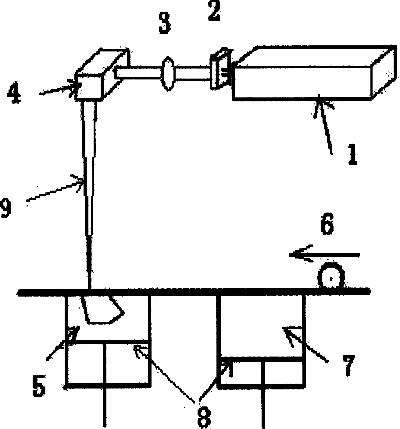
[0027] Such as figure 2 As shown, the metal parts selective laser melting rapid prototyping device adopts the front focusing method, including the beam focusing system composed of the laser 1, the beam expander 2, the focusing mirror 3, and the scanning galvanometer 4. The formed part cylinder 5 passes through the powder spreading roller 6 and powder The cylinders 7 are connected, and the molding cylinder 5 and the powder cylinder 7 are connected with a lifting piston 8. Forming part cylinder 5, powder spreading roller 6, powder cylinder 7, lifting piston 8, corresponding control drive components and computer constitute a powder laying system. Among them, laser 1 adopts semiconductor-pumped YAG laser and its attached power supply and water cooling system. The laser power is 100 watts, the wavelength is 1.06 μm, and the beam quality factor is M 2 = 1.5, the laser output spot is 3-6mm; the scanning galvanometer 4 adopts X and Y double galvanometers, the effective width is 24-3...

Embodiment 2

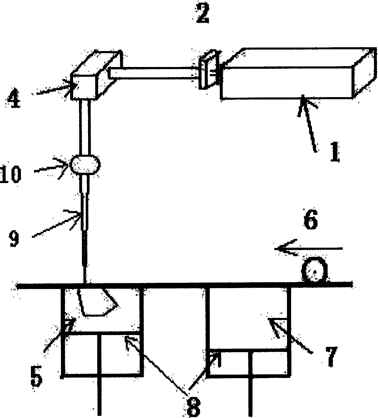
[0029] Such as image 3As shown, the selective laser melting rapid prototyping device for metal parts adopts the post-focusing method. The beam focusing system includes a beam expander 2, a scanning galvanometer 4 and an Fθ combination lens 10. The laser 1 adopts a fiber laser. Wherein, the focal length of the Fθ combination lens 10 is f=160-200 mm. The laser 9 is output from the laser 1, and after being expanded by the beam expander 2, it is first irradiated on the surface of the scanning galvanometer 4, and then focused by the Fθ combination lens 10, which is the interaction point between the laser 9 and the metal powder in the cylinder 5 of the molded part. The plane movement of the focus point can be realized by the slight swing of the scanning galvanometer 4 . The metal powder in the powder cylinder 7 is made of stainless steel powder material, and the particle size of the powder is less than 10 μm. Other structures are the same as in Embodiment 1.

Embodiment 3

[0031] Laser 1 in the selective laser melting rapid prototyping device for metal parts adopts a semiconductor-pumped YAG laser and its attached power supply and water cooling system. The laser power is 150 watts and the beam quality factor is M 2 =1.1; the alloy powder in the powder cylinder 7 is made of nickel-based alloy powder material, and the particle size of the powder is less than 10 μm. Other structures are the same as in Embodiment 1.


PUM

PropertyMeasurementUnit
Sizeaaaaaaaaaa

Abstract

The invention relates to laser melting rapid forming method in the metal parts precinct and its installation. The method includes that setting CAD geometric model, doing stratification variance and laying powder layer by layer to the CAD geometric mode, adopting laser with high power density and high light speed factor of merit to form focusing facula with the diameter which is from thirty millimeter to fifty millimeter by focusing of beams system, melting the metal or alloy powder layer by layer, piling to a metallurgy unite, and forming to a compact solid mass. The installation is made up of semiconductor pumping YAG laser or fiber laser, focusing of beams system, shaped part jar, and powder jar. The semiconductor pumping YAG laser or fiber laser is light path connected to the focusing of beams system, and focalized and scanned at the shaped part jar. The shaped part jar is connected to the powder jar by powder laying roller. The powder laying roller is connected to the driving motor. And the driving motor is connected to the computer. The advantages of the invention are that the beam mode is good; mechanical features of the processed metal parts is well; the dimensional precision and the surface finish are high; and its range of application is wide.

Description

technical field [0001] The invention relates to the field of forming and processing of metal parts, in particular to a rapid prototyping method and a device thereof by selective laser melting of metal parts. Background technique [0002] At present, there are two main types of rapid prototyping technologies for direct manufacturing of metal parts: (1) Selective Laser Sintering (SLS) (Selective Laser Sintering); (2) laser cladding-based metal parts direct forming technology. [0003] Selective laser sintering SLS (Selective Laser Sintering) method of manufacturing metal parts includes coating the surface of metal powder with low melting point metal or organic bonding material. The metal powder does not melt, and the formed three-dimensional entity is similar to a powder metallurgy sintered blank. The entity has a certain proportion of pores, generally about 60%, which is far from reaching 100% density. After the metal parts are formed, they need to u...

Claims


Application Information

Patent Timeline
IPC IPC(8): B22F7/06
Inventor 杨永强江泽文冯涛
Owner SOUTH CHINA UNIV OF TECH
Why Eureka
Try Eureka