
Method for controlling real-time database system

A control method, database technology, applied in the direction of comprehensive factory control, comprehensive factory control, electrical program control, etc.

Active Publication Date: 2009-09-30
SHANGHAI BAOSIGHT SOFTWARE CO LTD
View PDF0 Cites 12 Cited by
  • Summary
  • Abstract
  • Description
  • Claims
  • Application Information

AI Technical Summary

Problems solved by technology

[0006] The technical problem to be solved by the present invention is to provide a control method of a real-time database system, which ensures that the real-time database system provides Data integrity improves system reliability

Method used


Image

  • Method for controlling real-time database system

Examples


Embodiment Construction

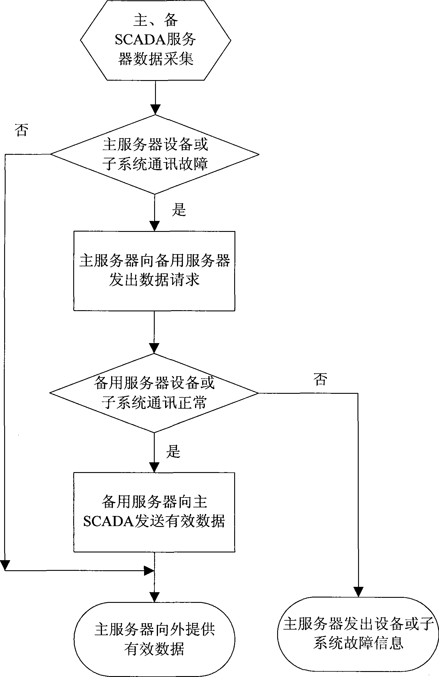
[0014] The real-time database system includes redundantly configured real-time servers or front-end communication processors, as well as devices and subsystems that communicate with the real-time servers or front-end communication processors respectively. The current real-time server or front-end communication processor for data collection and release is called the host , the standby real-time server or front-end communication processor is called the standby machine, when the host's own working state is abnormal, the real-time database system performs redundancy switching. A common FEP system consists of two mutually redundant FEP devices. The control method of the present invention is as follows: each FEP first independently collects data from each of the connected subsystems in a protocol conversion or data collection cycle. and protocol conversion. When the communication data link of a subsystem fails and the main FEP detects the failure (that is, if the subsystem returns t...


PUM


Abstract

The invention discloses a method for controlling a real-time database system. The method makes a standby machine in a data acquisition state and increases the real-time data judgment and synchronous process before a host machine finishes data acquisition and updates a self real-time database; if the host machine judges that the acquired data of a subsystem or equipment has problems through a communicating state, the host machine emits a data request of the data of the part to the standby machine through a data communication program of the standby machine; after the standby machine receives the request of the host machine, the standby machine also judges whether the acquired data has problems; if no, the data of the part is returned to the host machine; otherwise, a fault sign is returned to the host machine; and after the host machine receives the information returned by the standby machine, the host machine updates the real-time database and releases the data or emits an equipment fault signal. The controlling method removes the problem of wrong data caused by communication failures between the host machine and the subsystem or the equipment and ensures the data reliability and usability of the whole real-time database system.

Description

technical field [0001] The invention relates to a control method of a real-time database system. Background technique [0002] SCADA system is a computer-based production process control and scheduling automation system. It can monitor and control the operating equipment on site to realize various functions such as data collection, equipment control, measurement, parameter adjustment and various signal alarms. [0003] With the rapid development of equipment monitoring platform, comprehensive monitoring technology has been widely used in various industries, such as intelligent buildings, tunnel monitoring, rail transit and other fields. Different from the traditional equipment monitoring technology, the comprehensive monitoring is not only connected to the traditional on-site control equipment, such as PLC, RTU, DCS, etc. The comprehensive monitoring system also extends the monitoring scope to other control subsystems, such as power monitoring PSCADA, video surveillance sy...

Claims


Application Information

Patent Timeline
IPC IPC(8): G05B19/418
CPCY02P90/02
Inventor 贺志龙吴泾
Owner SHANGHAI BAOSIGHT SOFTWARE CO LTD
Learn More