Motor riveting structure

A motor and structure technology, applied in the field of riveting structure of motors, can solve the problems of wasting materials and man-hours, and achieve the effects of convenient production, avoiding waste of resources, and saving production costs

Active Publication Date: 2009-09-30
PANASONIC CORP +1
View PDF0 Cites 4 Cited by
  • Summary
  • Abstract
  • Description
  • Claims
  • Application Information

AI Technical Summary

Problems solved by technology

[0003] However, such an existing motor riveting structure has the problem of wasting materials and man-hours

Method used


Image

  • Motor riveting structure
  • Motor riveting structure
  • Motor riveting structure

Examples


Embodiment Construction

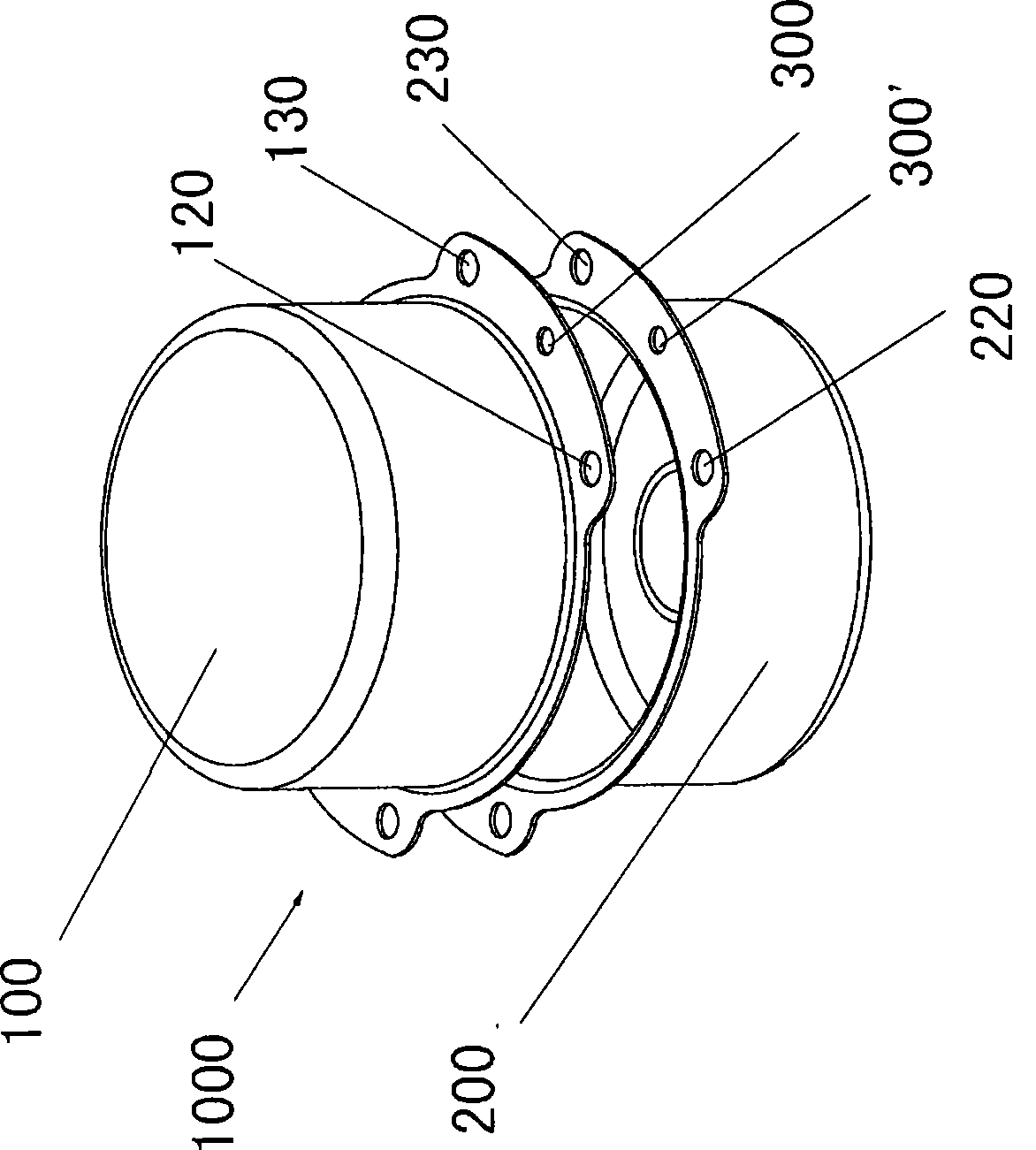
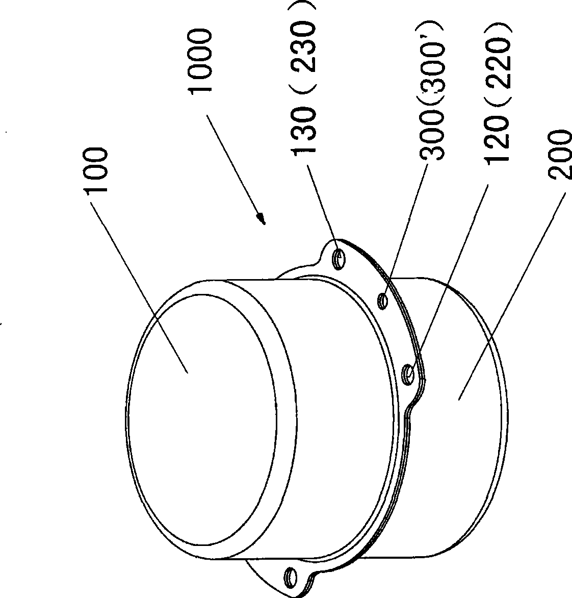
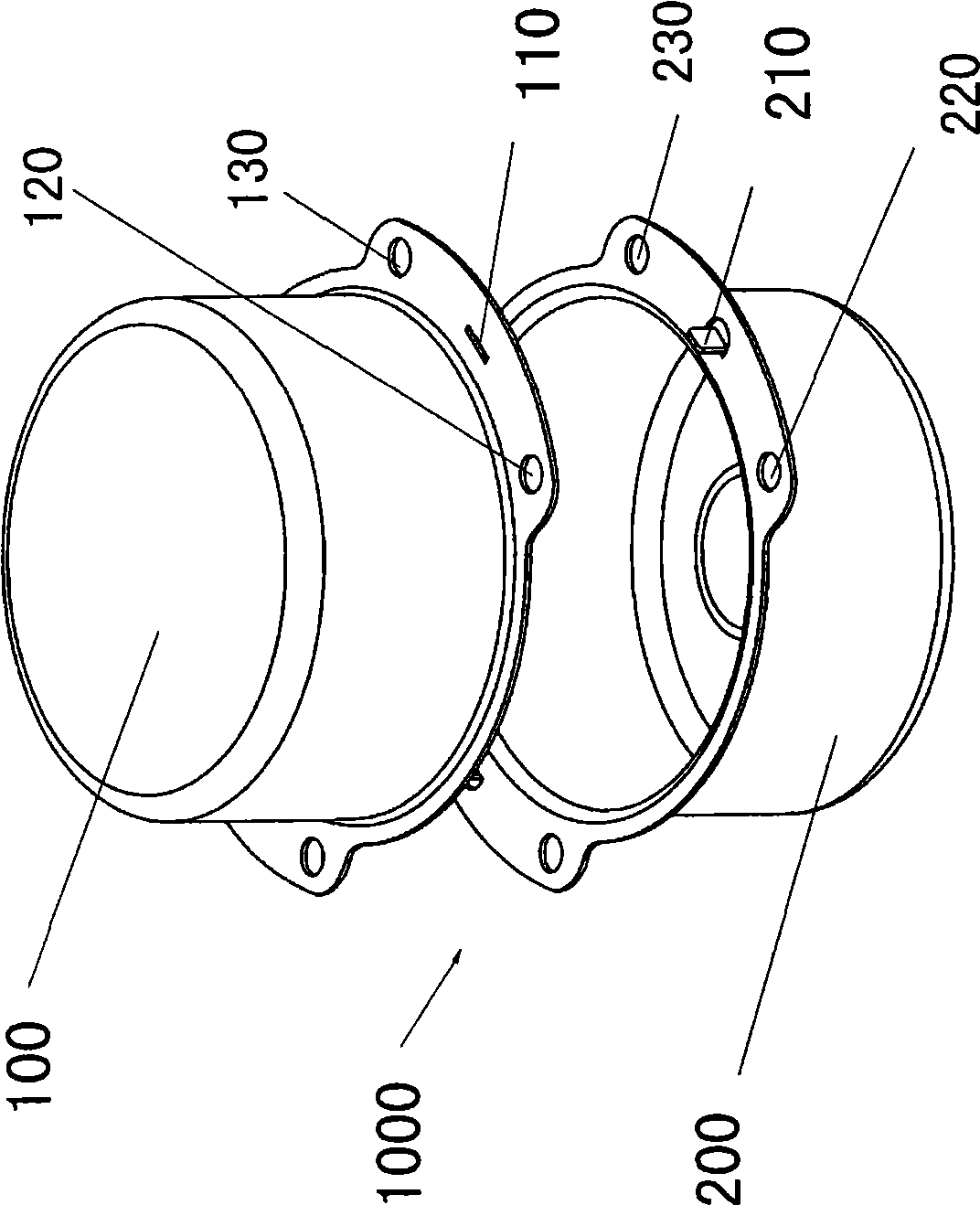
[0017] Such as Figure 2A , Figure 2B Shown is a schematic diagram of the first embodiment of the present invention. A slot 110 is provided on the side of the upper housing 100 of the motor, and a protrusion 210 is provided on the side of the lower housing 200, and the positions of the protrusion 210 and the slot 110 correspond to each other. When riveting the upper and lower shells, buckle the protrusions 210 into the grooves 110, then flatten the protrusions 210, make the protrusions 210 buckle the upper shell 100 of the motor after bending, thereby playing the role of riveting, and then use screws and nuts (Fig. (not shown in ) are respectively tightened and fixed on the screw holes 120, 220 and the screw holes 130, 230.

[0018] Such as Figure 3A , Figure 3B Shown is a schematic diagram of the second embodiment of the present invention. Cut off a small part of the side between the two screw holes 120, 130 on the side of the upper housing 100 of the motor, leaving a...


PUM


Abstract

The invention provides a motor riveting structure, which comprises an upper shell and a lower shell of a motor, and is characterized in that: the upper and lower shells of the motor are respectively provided with mutually matched enclosing and clamping structures in a mode of integrated forming. Through the structure, when a motor is riveted through the mutually matched enclosing and clamping structures on the upper shell and the lower shell, as long as the enclosing and clamping structures are aligned, positions of holes of screws for mounting the motor onto a product are ensured to be consistent to play a role in positioning. Because rivets are not needed, materials are saved; and meanwhile, the rivets are not needed to be placed on the riveting position, and the positions of the holes of the screws used for mounting the motor onto the product are not needed to be adjusted after the rivets are placed, so the labor hour is reduced.

Description

technical field [0001] The invention relates to a motor, in particular to a riveting structure of the motor. Background technique [0002] Such as Figure 1A , Figure 1B Shown is the riveting structure of the existing motor housing. The motor 1000 has two housings, an upper housing 100 and a lower housing 200, with screw holes 120, 130 and screw holes 220, 230, respectively. Combining holes 300 and 300' are formed between the screw holes 120, 130 and between the screw holes 220, 230. During installation, first put the rivets (not shown in the figure) in the joint holes 300 and 300', and then use a hydraulic press to flatten the rivets, so that the upper casing 100 and the lower casing 200 of the motor can be firmly combined; Screws and nuts (not shown in the figure) are respectively tightened and fixed on the screw holes 120, 220 and the screw holes 130, 230. [0003] However, such a conventional motor riveting structure has the problem of wasting materials and man-hour...

Claims


Application Information

Patent Timeline
IPC IPC(8): H02K5/04
Inventor 朱世平李纯文吴炎浓
Owner PANASONIC CORP
Why Eureka
Try Eureka