Method for growing photosynthetic organisms

A technology of photosynthetic organisms and biofuels, applied in separation methods, biofuels, biological raw materials, etc.

Inactive Publication Date: 2009-09-30
SEAMBIOTIC LTD
View PDF6 Cites 16 Cited by
  • Summary
  • Abstract
  • Description
  • Claims
  • Application Information

AI Technical Summary

Problems solved by technology

Although the CO exchanged with the natural cycle 2 amount compared to anthropogenic CO 2 Emissions are small, but atmospheric CO 2 long life (50-200 years) and natural CO 2 The difference between the slow rates of the sequestration process leads to CO 2 accumulation in the atmosphere

Method used


Image

  • Method for growing photosynthetic organisms
  • Method for growing photosynthetic organisms
  • Method for growing photosynthetic organisms

Examples


Embodiment I

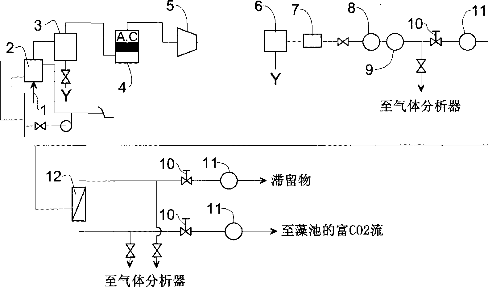
[0064] Example 1 - Membrane Separation

[0065] One of the unique features of CMSM fabrication technology is the ability to tightly control the membrane permeability / selectivity combination to suit various applications. In this regard, the membranes tested in this work were prepared to achieve the optimum permeability / selectivity combination for air separation.

[0066] The results stated below are based on an effective separation area of ​​3.4m made of approximately 10,000 carbon hollow fibers 2 Obtained from a test assembly open at one end.

[0067] Permeability assays and air enrichment assays are performed with a single gas: N 2 , O 2 , CO 2 and SF 6 . (The last gas is used to determine the molecular sieve properties of the membrane). The tests were carried out at room temperature and at feed pressures of up to 5 bar.

[0068] Two sets of experiments were performed:

[0069] - Permeability determination using pure gas;

[0070] - Air separation.

[0071] Consi...

Embodiment II

[0075] Example II - Transport System

[0076] In one embodiment of the transport system for transporting the treated flue gas to the microalgae cultivation area, the following components are required:

[0077] 1) Main gas pipelines suitable for transporting gases containing carbon dioxide;

[0078] 2) The primary gas manifold located close to the algae field;

[0079] 3) Mains for conveying carbon dioxide-containing gas from the main gas line to the primary gas manifold; and

[0080] 4) A plurality of secondary discharge lines extending from the primary gas manifold into the pond and including vents for delivering carbon dioxide rich gas to the algae.

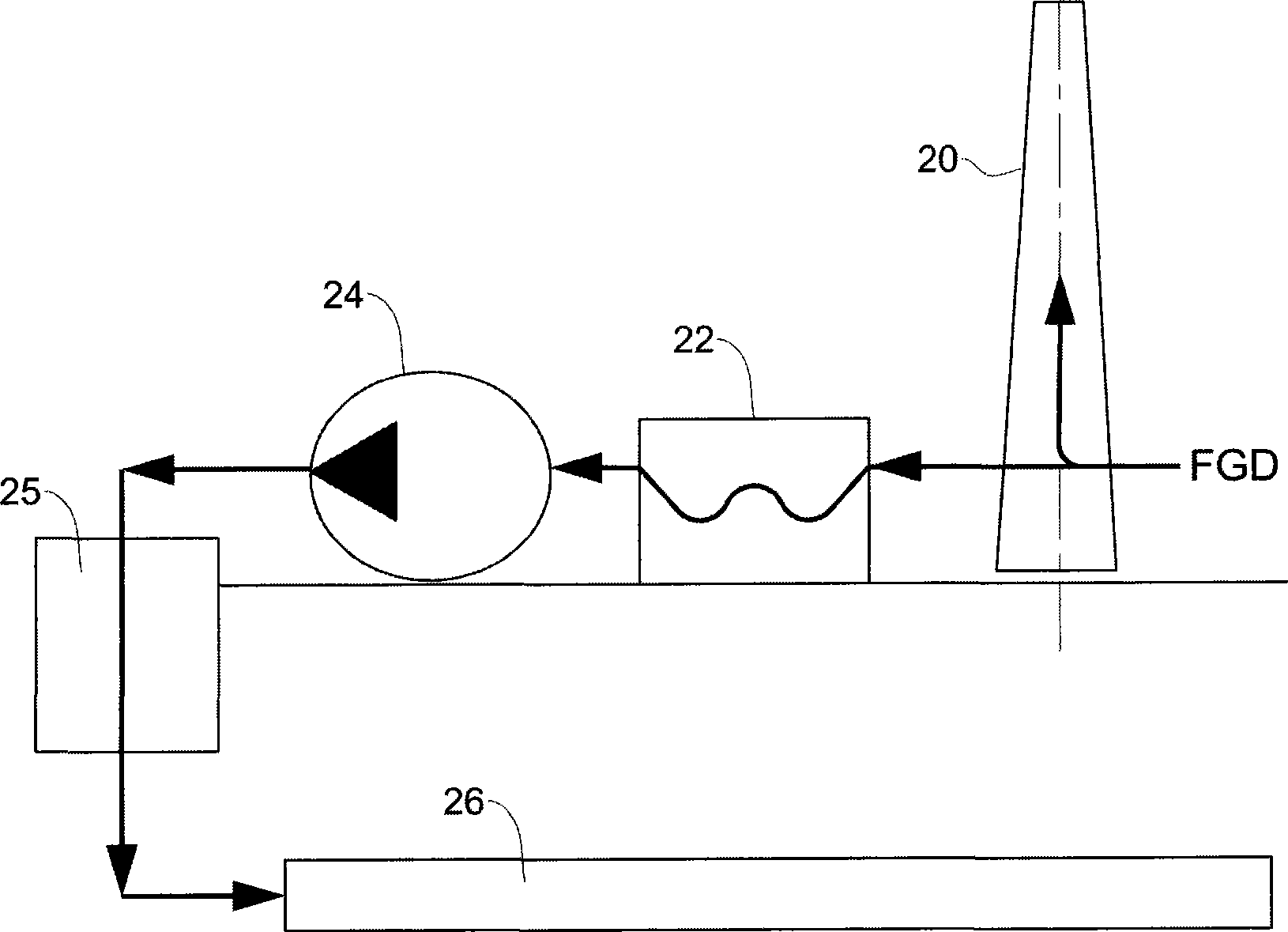
[0081] One of the major commercial considerations is the supply of CO 2 The distance between the power plant and the seaweed field. This distance determines the selection to be made. The greater the amount of "parasitic" gas to be transferred, the more expensive the piping to use and the greater the energy consumption du...

Embodiment III

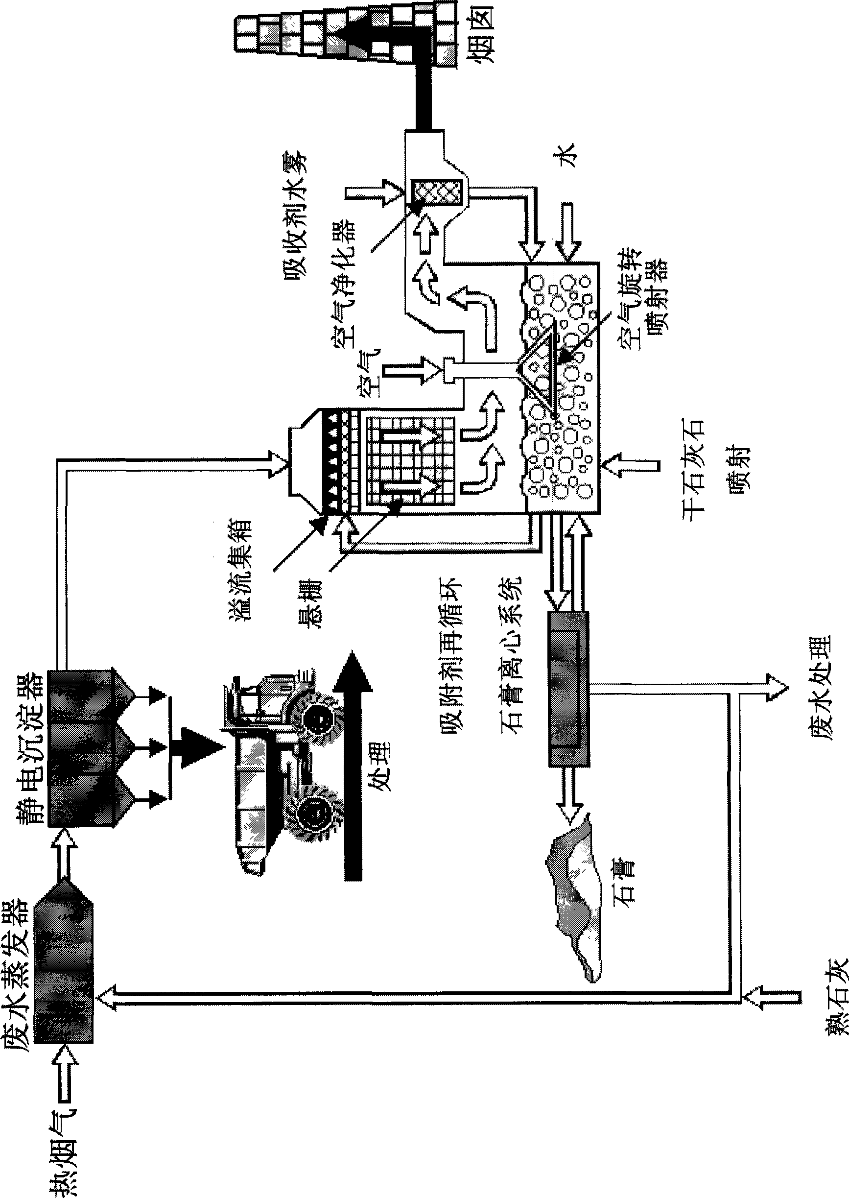
[0104] Example III - Inflation

[0105] The supply of flue gas into the pool is carried out by means of an aeration device.

[0106] The inflatable device is manufactured from a chemically stable polymeric material as the inflatable component. A preferred embodiment of the aerator is the KREAL tubular aerator (porous) (Russian Patent No. 32487). The inflator components are made in the form of LPP pipes (low pressure polyethylene), in which the inflators are fixed in pairs by polyamide T-tubes.

[0107] The inflatable assembly is implemented with LPP pipes (d=110-160mm), and the inflators are fixed in pairs on the LPP pipes through plastic trilling. The module width is 1.1m; the spacing between the aerators is 1.5-4m. Changing the spacing between the inflators allows varying the injection intensity over a wide range, ensuring optimum CO 2 model.

[0108] The use of polymeric materials in the inflator components reduces assembly time and increases the operational life of ...


PUM

PropertyMeasurementUnit
widthaaaaaaaaaa

Abstract

A method of growing photosynthetic organisms comprising providing the organisms with flue gases from a fossil-fuel power plant, the gases being previously treated by desulfurization. The carbon dioxide (CO2) concentration of the flue gases may be increased over the CO2 concentration as released from the power plant. Also disclosed is a method for producing Omega fatty acids and bio-fuels comprising growing microalgae by providing said microalgae with flue gases from a fossil-fuel power plant.

Description

technical field [0001] The present invention relates to photosynthetic organisms for CO in flue gas from power stations 2 biotransformation. Background technique [0002] One of the most recent and future environmental concerns is atmospheric greenhouse gases, especially carbon dioxide (CO 2 ) increased significantly. Atmospheric CO since the Industrial Revolution 2 Concentrations have been steadily increasing. It has been widely recognized that atmospheric CO 2 Concentrations increased from 315ppm in 1959 to 370ppm in 2001, while atmospheric CO 2 The concentration is about 280 ppm. It is reported that half of the greenhouse effect responsible for global warming is caused by increasing CO 2 caused by the concentration. Although the CO exchanged with the natural cycle 2 amount compared to anthropogenic CO 2 Emissions are small, but atmospheric CO 2 long life (50-200 years) and natural CO 2 The difference between the slow rates of the sequestration process leads to...

Claims


Application Information

Patent Timeline
Patent Type & Authority Applications(China)
IPC IPC(8): B01D53/84A61K31/202C10L1/00
CPCY02E50/17A61K31/202Y02E50/13B01D2313/40B01D2313/24B01D53/85C10G2300/1011B01D71/021B01D63/02Y02E50/10Y02P30/20Y02A50/20B01D53/84B82Y30/00C10L1/00
Inventor 赫尔曼·维斯
Owner SEAMBIOTIC LTD
Why Eureka
Try Eureka