Control assembly for interlocked sockets

A technology for controlling components and sockets, applied in the direction of control components, mechanical control devices, control/regulation systems, etc., to solve problems such as difficulty in understanding the open or closed state of circuit breakers

Inactive Publication Date: 2009-09-30
PALAZZOLI
View PDF0 Cites 0 Cited by
  • Summary
  • Abstract
  • Description
  • Claims
  • Application Information

AI Technical Summary

Problems solved by technology

[0004] Regardless of what these applications claim, the main disadvantage of conventional rotary switch devices is that the color of the knob and its indicator and the background color of the "0" and "I" markings on it are always the same, at a certain distance or in the Low light levels can be difficult to understand with certainty if a circuit breaker is open or closed

Method used


Image

  • Control assembly for interlocked sockets
  • Control assembly for interlocked sockets
  • Control assembly for interlocked sockets

Examples


Embodiment Construction

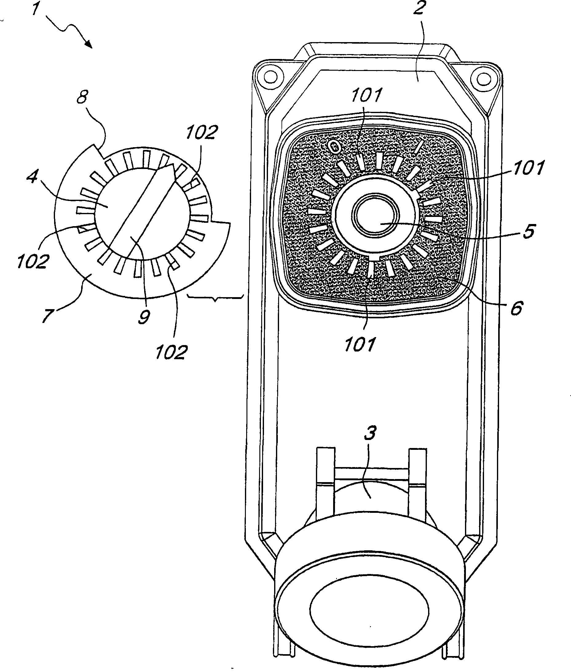
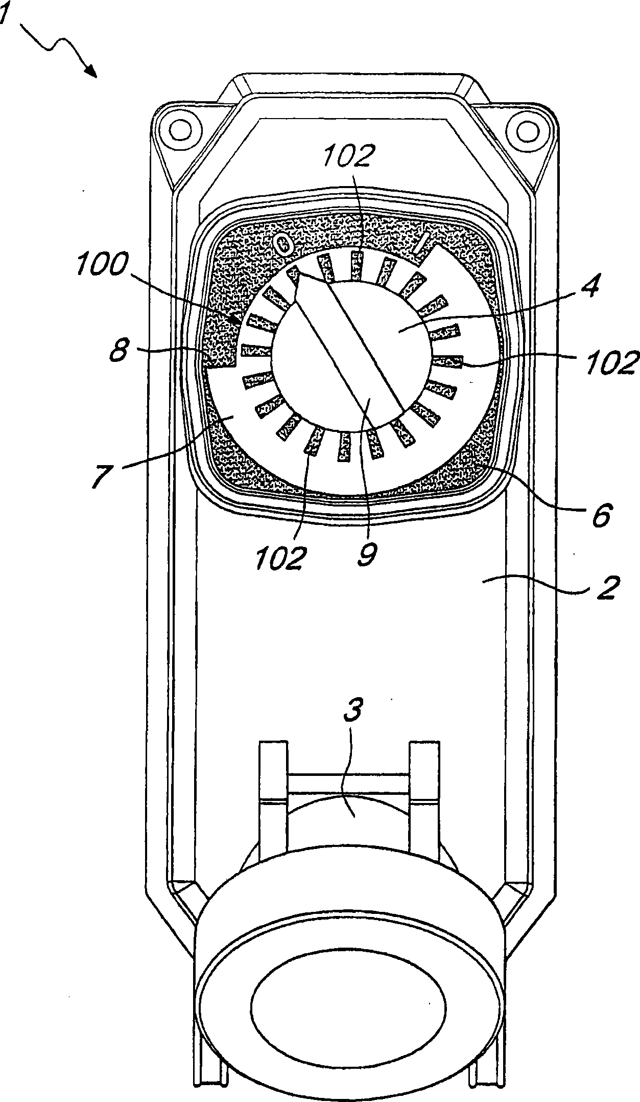
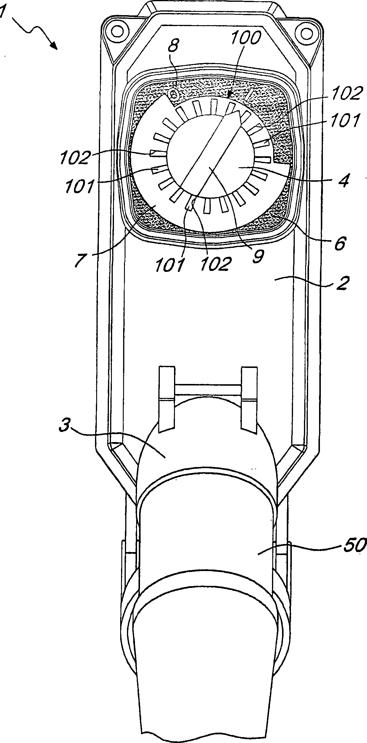
[0016] Reference attached Figure 1-3 , the control assembly is incorporated in the interlocking socket, the control assembly is generally indicated by the reference numeral 1, the control assembly includes a support structure 2 made of insulating, impact-resistant and self-extinguishing polymer, the switchgear (not shown in the drawings ) and the socket 3 are assembled on the support structure 2.

[0017] Said switching device is actuated by a knob 4 and is connected to the socket 3 through a safety device (not shown in the figures). The safety device prevents the socket 3 from being live before the plug 50 is fully inserted and prevents the disengagement of the plug 50 while the socket 3 is still live, in a manner known per se.

[0018] According to the present invention, the rotary switch device incorporated in the interlock socket 1 has a visual indication device 100 which makes the open / closed state of the rotary switch device stand out and can be detected by rotation of...


PUM


Abstract

A control assembly for interlocked sockets includes a rotary breaker which is actuated by a knob and is mounted on a supporting structure. The control assembly includes a visual indication means which has the purpose of highlighting the open / closed state of the rotary breaker as a consequence of rotations of the knob.

Description

technical field [0001] The present invention relates to control assemblies for interlocking receptacles. Background technique [0002] As is known, operations for opening and closing circuits in industrial electrical systems are always carried out by using a rotary switchgear assembly basically consisting of a rotary-type circuit breaker controlled by a knob, in compliance with a specific standard, the circuit breaker The circuit breaker is provided with an indicator pointing to the "0" mark when the circuit breaker is in the open state or to the "I" mark when the circuit breaker is in the closed state. [0003] Rotary switch units are very flexible in use, in addition, rotary switch units are used as circuit breaker disconnectors in low voltage industrial electrical systems, they are in fact often an integral part of interlocking socket outlets. In order to ensure the safety of the operator and the integrity of all high-voltage installations, interlocked socket outlets inc...

Claims


Application Information

Patent Timeline
Patent Type & Authority Applications(China)
IPC IPC(8): G09F11/23H01R13/707G05G1/015H01H9/16
CPCH01H9/16G09F11/23H01R13/717G05G1/015
Inventor B·莱维
Owner PALAZZOLI
Why Eureka
Try Eureka