A multi-strand cable laying spacer

A spacer and cable technology, applied in the direction of electrical components, etc., can solve the problems of maintenance and replacement, inability to tension cables, and high laying costs

Active Publication Date: 2020-10-20
江苏华淼电子科技有限公司
View PDF13 Cites 0 Cited by
  • Summary
  • Abstract
  • Description
  • Claims
  • Application Information

AI Technical Summary

Problems solved by technology

[0002] At present, when laying pipelines, it is necessary to lay and fix cables in the pipe gallery. The current cable fixing in the pipe gallery mainly uses splints to fix the cables, and the cables are fixed and laid on the side walls through the splints. , due to the large number of cables, the length of the splints used is relatively long, and the mutual winding, installation and fixing are limited, so the space cannot be used reasonably. Secondly, the fixation of the splints cannot form a tension effect on the cables. At the same time, when performing cable maintenance, it is necessary to dismantle the multi-strand cables on the splint synchronously, which is time-consuming and laborious. Other existing cable laying devices also use similar methods, such as using wire boxes to lay cables. planning, the laying cost is high, the maintenance and repair of cables is difficult, and the faulty cables cannot be quickly identified and detected, and repaired and replaced
[0003] Publication No. CN207612026U discloses a multi-bundle cable transit assembly, including a waterproof sleeve pre-buried in the wall. One end of the waterproof sleeve is provided with an annular transit port along its end face, and the center of the transit port is The through hole forms an inspection port, and an inspection plug is provided on the inspection port; several threading ports are arranged at intervals on the transit port, and a group of single-bundle cable transits are arranged in each threading port. The ring-shaped deformed part in the mouth, the fastening device to fix the deformed part, and the filling part filled in the deformed part have a complex structure and lack a pulling structure. At the same time, it is inconvenient to install and fix in the pipe gallery, so it is not suitable for The laying interval and tension environment of multi-strand cables in the pipe gallery

Method used


Image

  • A multi-strand cable laying spacer
  • A multi-strand cable laying spacer
  • A multi-strand cable laying spacer

Examples


Embodiment Construction

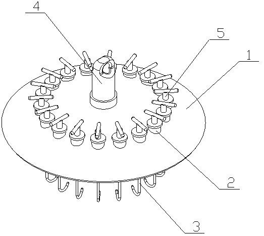
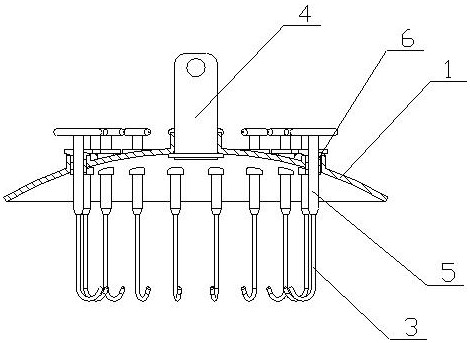
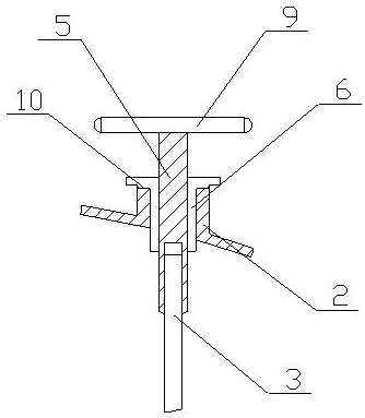
[0017] A multi-strand cable laying spacer of the present invention is realized in this way: a multi-strand cable laying spacer of the present invention consists of a main disc body 1, a fixing sleeve 2, a pulling rod 3, a main fixing column 4, and a main pulling rod 5 , screw sleeve 6, fixed ring 7, limit card slot 8, deflection rod 9 and limit boss 10, the fixed ring 7 is placed in the middle of the main disc body 1 and runs through the main disc body 1, the main fixed column 4 is placed In the fixing ring 7, one end is clamped on the main disk body 1 through the limit ring, and the other end protrudes from the main disk body 1. The other end of the main fixing column 4 has a fixed installation hole, and the main disk body 1 is Spherical crown structure, a plurality of fixed sleeves 2 are placed on the main disk body 1, the fixed sleeves 2 are distributed in a circle, the end surface of the fixed sleeve 2 is radially opened with a limit card slot 8, and a plurality of screw sl...


PUM


Abstract

A multi-strand cable laying spacer plate disclosed in the invention is a pipe rack cable laying spacer plate capable of spacing and supporting multiple cables and separately pulling the cables, and ischaracterized in that a fixed ring is placed in the middle part of a main plate body and penetrates through the main plate body; a main fixed column is placed in the fixed ring, one end of the main fixed column is clamped on the main plate body through a spacing ring, and the other end of the main fixed column extends out of the main plate body; the other side of the main fixed column is providedwith a fixed mounting hole; the main plate body has a spherical cap structure; multiple fixed sleeves are arranged on the main plate body and are circumferentially distributed; the end face of the fixed sleeve is radially provided with limit clamping groove; a plurality of screw sleeves are correspondingly arranged in the fixed sleeves; the mouth part of the screw sleeve is turned over to form alimit structure; and a limit boss is disposed on the outer side of the screw sleeve and is correspondingly clamped with the limit clamping groove.

Description

technical field [0001] The invention relates to a spacer for laying multi-strand cables, which relates to a spacer for pulling the multi-strand cables at intervals during the laying of multi-strand cables in a pipe gallery, and belongs to the field of electric facilities. Specially designed a cable laying spacer for pipe gallery that can support multiple cables at intervals and pull the cables independently. Background technique [0002] At present, when laying pipelines, it is necessary to lay and fix cables in the pipe gallery. The current cable fixing in the pipe gallery mainly uses splints to fix the cables, and the cables are fixed and laid on the side walls through the splints. , due to the large number of cables, the length of the splints used is relatively long, and the mutual winding, installation and fixing are limited, so the space cannot be used reasonably. Secondly, the fixation of the splints cannot form a tension effect on the cables. At the same time, when p...

Claims


Application Information

Patent Timeline
IPC IPC(8): H02G3/30
CPCH02G3/30
Inventor 朱元彩
Owner 江苏华淼电子科技有限公司
Why Eureka
Try Eureka