Determination and use of power system sensitivities for power flow control

一种电力潮流、电力系统的技术,应用在系统集成技术、信息技术支持系统、电气元件等方向,能够解决没有考虑影响等问题

Active Publication Date: 2009-09-30
HITACHI ENERGY LTD
View PDF1 Cites 5 Cited by
  • Summary
  • Abstract
  • Description
  • Claims
  • Application Information

AI Technical Summary

Problems solved by technology

[0008] With this fast but localized control, the control path is prevented from being overloaded, as traffic can be diverted by the PFC, but the impact on other parts of the network is not considered

Method used


Image

  • Determination and use of power system sensitivities for power flow control
  • Determination and use of power system sensitivities for power flow control
  • Determination and use of power system sensitivities for power flow control

Examples


Embodiment Construction

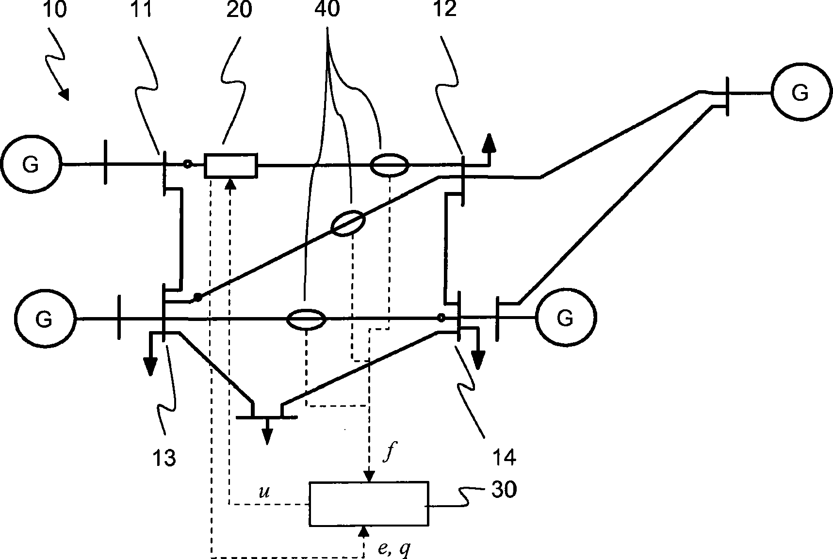
[0028] figure 1 A mesh power grid 10 is shown having a plurality of parallel flow paths or transmission channels. Hereinafter, the term "parallel flow path" denotes any two flow paths interconnecting two nodes or areas 11 , 12 , 13 , 14 in the network 10 . for example, figure 1 , nodes 11 and 12 are connected by parallel flow paths 11-12, 11-13-12 and 11-13-14-12. The power grid is an AC network with multiple sources G and loads (shown as arrows) interconnected in a ring configuration. A power flow controller (PFC) 20 is arranged to control the flow of power in the flow paths 11 - 12 , but will also affect the flow through the aforementioned alternative parallel flow path between nodes 11 and 12 .

[0029] In the sense of the present invention, there are many different types of PFCs available for controlling power flow, wherein different types of PFCs control flow in different ways via different control operations. For example, PFC operates by injecting a voltage in series...


PUM


Abstract

The present invention is concerned with the computation of power system sensitivities from power flow parameters and control parameters of a Power Flow Control Device (PFC). To this end, control parameter variations are applied to or generated by a PFC (20), and comprise variations in a control input u, a control effort e (injected series voltage, inserted series reactance), or a control effect q (power flow, active power transfer, phase-shift, current). A power flow response measuring unit (40) measures a variation of a power flow response such as current, active or apparent power, in a way sufficiently synchronized with the control parameter variation to allow establishing an unambiguous causal relationship or correspondence in the form of a power system sensitivity. The latter may be on-line adapted to continuously reflect an updated aspect of the power system behaviour, and thus enable an improved, fast and reliable power flow control in power systems comprising a meshed power network with two parallel flow paths or corridors connecting two areas or sub-systems.

Description

technical field [0001] The invention relates to the field of power flow control in power systems comprising multiple transmission channels interconnecting different areas. Background technique [0002] With the ongoing deregulation of electricity markets, load shifting and transfer of electricity from distant generators to local consumers has become common practice. As utilities compete with new demands to optimize assets, substantially increased electricity is transmitted over existing networks, sometimes causing congestion, transmission bottlenecks, and / or oscillations in parts of the transmission system. In this regard, transmission grids are highly dynamic and power flows over alternative transmission paths may need to be redistributed in response to changing network conditions, loads or power injected by generating units. [0003] Therefore, network-based control of redirection and uniform redistribution of power flow in transmission systems without generation redispat...

Claims


Application Information

Patent Timeline
Patent Type & Authority Applications(China)
IPC IPC(8): H02J3/24
CPCY02E60/728H02J3/005Y04S10/265H02J3/24Y02E60/00Y04S10/00Y04S10/22Y02E40/70H02J3/242H02J3/007
Inventor B·伯格伦M·拉森T·本格特森P·科巴A·奥达洛夫
Owner HITACHI ENERGY LTD
Why Eureka
Try Eureka