Image-based on-line detection and compensation system and method for cutting tools

A compensation method and tool technology, applied in the field of tool processing, can solve problems such as implementation difficulties

Inactive Publication Date: 2009-10-07
BEIJING UNIV OF POSTS & TELECOMM
View PDF0 Cites 72 Cited by
  • Summary
  • Abstract
  • Description
  • Claims
  • Application Information

AI Technical Summary

Problems solved by technology

In fact, due to the existence of a large number of vibrations in the tool processing site, the tool and the processed parts are constantly shaking during the process, so it has alwa

Method used


Image

  • Image-based on-line detection and compensation system and method for cutting tools
  • Image-based on-line detection and compensation system and method for cutting tools
  • Image-based on-line detection and compensation system and method for cutting tools

Examples


Embodiment Construction

[0016] The present invention will be described below in conjunction with the accompanying drawings. It should be understood that the following examples are illustrative only and not limiting.

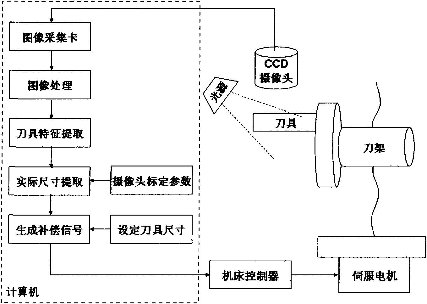
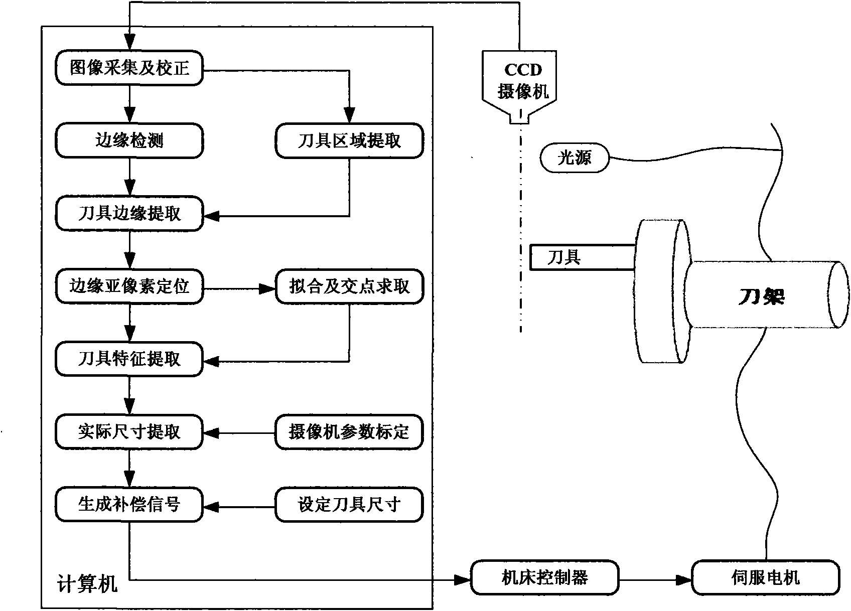
[0017] refer to Figure 1-6 , to illustrate the system and method for online tool image detection and compensation of the present invention.

[0018] The working process of the online detection and compensation system of the present invention is as follows:

[0019] (1) An imaging device is arranged, and an image of a tool installed on a machine tool is captured by the imaging device. Before the tool processing on the lathe starts, the CCD camera is used to obtain the current shape image of the tool at a given position with the cooperation of the auxiliary light source. Preferably, the camera is periodically collected in the process of acquiring the image of the tool shape, for example, a preset processing time can be set, and when the tool cuts for a certain long time, the image of ...


PUM


Abstract

The invention discloses a kind of image-based online detection and compensation method for cutting tools which is used for online detection of the tool wear amount on the machine tool and compensation based on the wear amount, including the following steps: lay out camera equipment, and take the photo of the cutting tools installed on the machine tool through the camera; calibrate the images taken; extract the cutting tool features; convert the cutting tool features into the actual sizes through the camera parameter calibration; compare the actual sizes with the pre-set cutting tool sizes to generate compensation signals; supply the referred compensation signals to the machine tool controller and use machine tool controller to drive the servo motor to compensate for the deviation generated by cutting tool wear.

Description

technical field [0001] The invention relates to the field of tool processing, in particular to an image-based online tool detection and compensation system and method. Background technique [0002] In the field of CNC machine tool processing in the prior art, automatic control is adopted. After setting the processing route and processing amount of the tool, the tool executes the processing process of the part according to the established program. However, there is a problem with this machining method because the tool wears out after cutting a large number of parts. As the amount of tool wear increases, after exceeding a certain critical value, all the parts processed by the tool will become waste or substandard products. This has just produced the waste of a large amount of resources, has increased production cost. [0003] Therefore, it is desired to provide an online tool detection and compensation system and method, which can detect the wear amount of the tool in real t...

Claims


Application Information

Patent Timeline
IPC IPC(8): B23Q15/16B23Q17/09B23Q17/24B23Q17/20G05B19/404
Inventor 王晨升常红星
Owner BEIJING UNIV OF POSTS & TELECOMM
Why Eureka
Try Eureka