A polishing disk with internal circulated cooling

A polishing disc and internal circulation technology, used in surface polishing machine tools, grinding/polishing equipment, abrasives, etc., can solve the problems of droplet splashing, inappropriate precision machining occasions, involving liquid collection, etc., to achieve easy layout , the effect of easy processing

Active Publication Date: 2009-10-07
HWATSING TECH
View PDF0 Cites 34 Cited by
  • Summary
  • Abstract
  • Description
  • Claims
  • Application Information

AI Technical Summary

Problems solved by technology

[0006] Traditional cooling methods, such as spraying, will cause splashing of droplets and in

Method used


Image

  • A polishing disk with internal circulated cooling
  • A polishing disk with internal circulated cooling
  • A polishing disk with internal circulated cooling

Examples


Embodiment 1

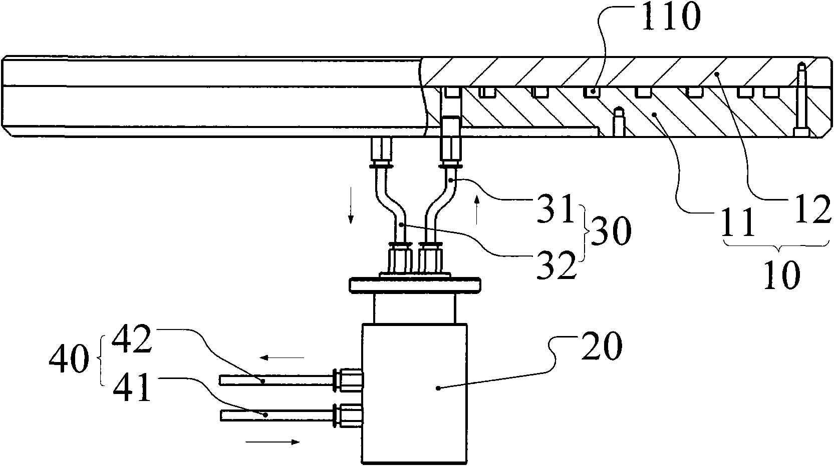
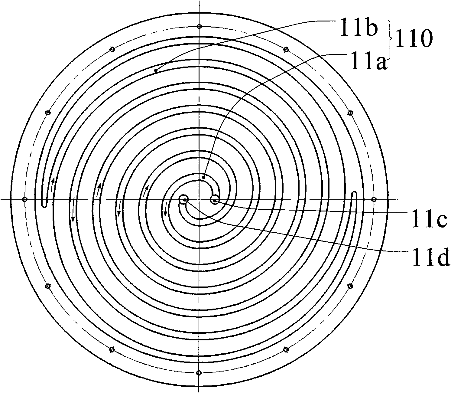
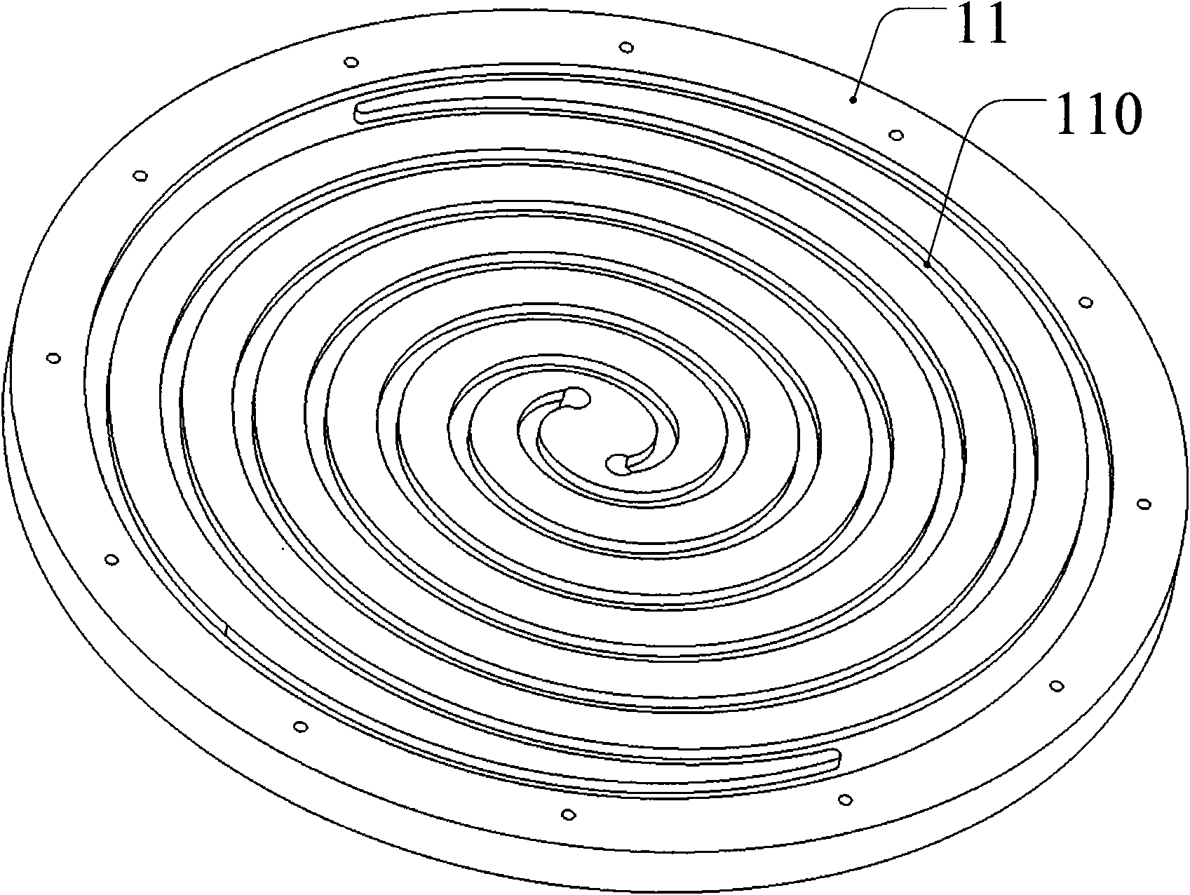
[0020] An internal circulation cooling polishing disc, such as figure 1 As shown, the internal circulation cooling polishing disc is mainly composed of a combined polishing disc 10, a rotary joint 20, an internal piping system 30 and an external piping system 40. The combined polishing disc 10 consists of an upper disc 12 and a lower disc 11 composition, the bottom plate 11 is provided with a spiral circulation groove 110 (such as image 3 as shown, image 3 is the three-dimensional diagram of the circulation groove of the bottom wall), including the liquid inlet spiral groove 11a and the liquid return spiral groove 11b, the liquid inlet spiral groove 11a and the liquid return spiral groove 11b are interlaced and symmetrical to the center, and the two spiral grooves The slots meet at the outermost ring (eg figure 2 as shown, figure 2 is the schematic diagram of the circulation groove of the lower wall), the starting point of the liquid inlet spiral groove 11a is provided ...


PUM


Abstract

The present invention discloses a polishing disk with internal circulated cooling, which pertains to the technical field of polishing equipment. This polishing disk mainly comprises combined polishing disk, swivel joint, internal piping system and external piping system. The combined polishing disk consists of upper disk and lower disk. On the lower disk, circular and spiral grooves are arranged, including solution feeding spiral groove and solution returning spiral groove. The two grooves are interleaved and centrally symmetric and converge on the outermost circle. At the starting point of the solution feeding spiral groove, a through threaded hole is arranged as water inlet. At the starting point of the solution returning spiral groove, a through threaded hole is arranged as water outlet. The lower disk and upper disk are connected with bolts on outer edge. Circular grooves are formed inside the combined polishing disk. The spiral circular grooves in the present invention are easily processed. As the grooves adopt a centrally symmetric structure, the dynamic equilibrium is not affected. The inlet and outlet of the cooling groove are both in the middle of the polishing disk to realize the circular cooling of the coolant that enters and leaves the polishing disk from its middle part, creating convenience for the arrangement of the piping system.

Description

technical field [0001] The invention belongs to the technical field of polishing equipment, in particular to an internal circulation cooling polishing disc. Background technique [0002] Polishing equipment, especially chemical mechanical polishing equipment is a kind of precision processing equipment, and the relative movement required for the polishing process is generated by the relative movement between the polishing head and the polishing disc. The workpiece to be polished is placed in the polishing head, the polishing pad is pasted on the surface of the polishing disc, and a certain pressure is applied to the workpiece through the polishing head, so that the workpiece is pressed on the surface of the polishing pad, relying on the relative movement between the workpiece and the polishing pad, and by means of the polishing liquid The abrasive grains in the abrasive can finish the surface of the workpiece. [0003] During the polishing process, due to the friction betwee...

Claims


Application Information

Patent Timeline
IPC IPC(8): B24D7/10B24B29/00
Inventor 路新春赵德文王同庆雒建斌
Owner HWATSING TECH
Why Eureka
Try Eureka