Rotary cylinder using planar end oil film for sealing hydraulic slipring

A hydraulic slip ring and oil film sealing technology, applied in the field of CNC machine tools, can solve the problem of low speed and achieve the effects of small energy loss, simple structure and good reliability

Active Publication Date: 2009-10-07
湖南哈工机器人研究院有限公司
View PDF0 Cites 2 Cited by
  • Summary
  • Abstract
  • Description
  • Claims
  • Application Information

AI Technical Summary

Problems solved by technology

[0006] The present invention aims at the shortcomings of the existing rotary oil cylinders that the rotation speed is not high, and proposes a rotary oil cylinder that uses a plane end face oil film to seal the hydraulic slip ring

Method used


Image

  • Rotary cylinder using planar end oil film for sealing hydraulic slipring
  • Rotary cylinder using planar end oil film for sealing hydraulic slipring
  • Rotary cylinder using planar end oil film for sealing hydraulic slipring

Examples


specific Embodiment approach 1

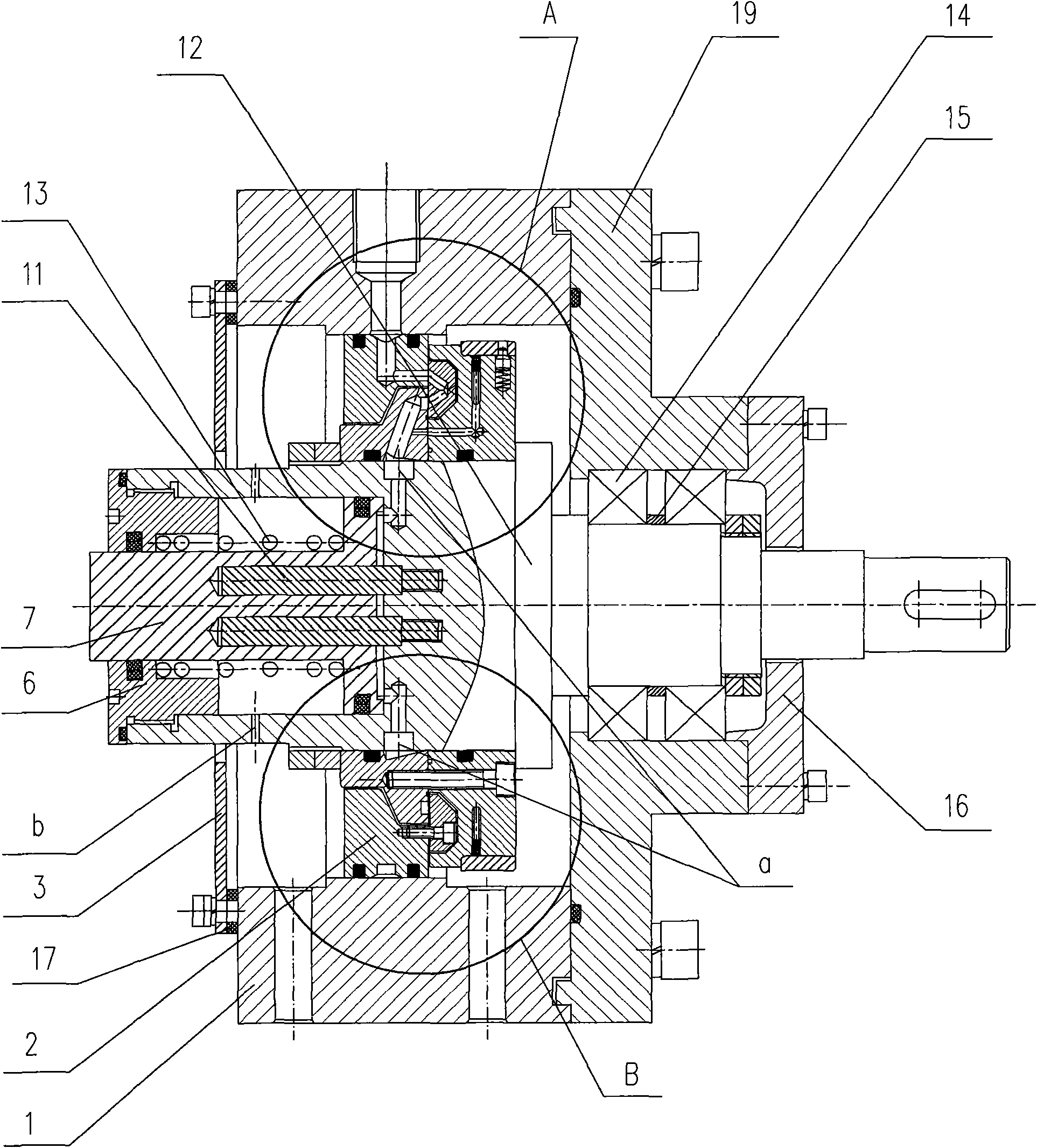
[0011] Specific implementation mode one: combine figure 1 Describe this embodiment. This embodiment is composed of a hydraulic slip ring 2, a cylinder head 6, a piston 7, a drive pin 11, a shaft 12, a spring 13, a bearing 14 and a housing. One end of the shaft 12 is connected to the motor through a coupling, and the shaft The end of the other end of 12 has a cylinder body, and the end face in the cylinder body of the shaft 12 is provided with a hole, and one end of the drive pin 11 and the hole on the end face of the cylinder body of the shaft 12 adopt threaded cooperation, and the other end of the drive pin 11 The hole on the end face of the head of the piston 7 adopts clearance fit. The cylinder head 6 is set on the piston rod of the piston 7 and seals the cylinder body of the shaft 12. The spring 13 is set on the piston rod of the piston 7 and supported on the cylinder head 6 and the piston. 7 Between the heads, the shaft 12 is fixedly connected to the casing through the b...

specific Embodiment approach 2

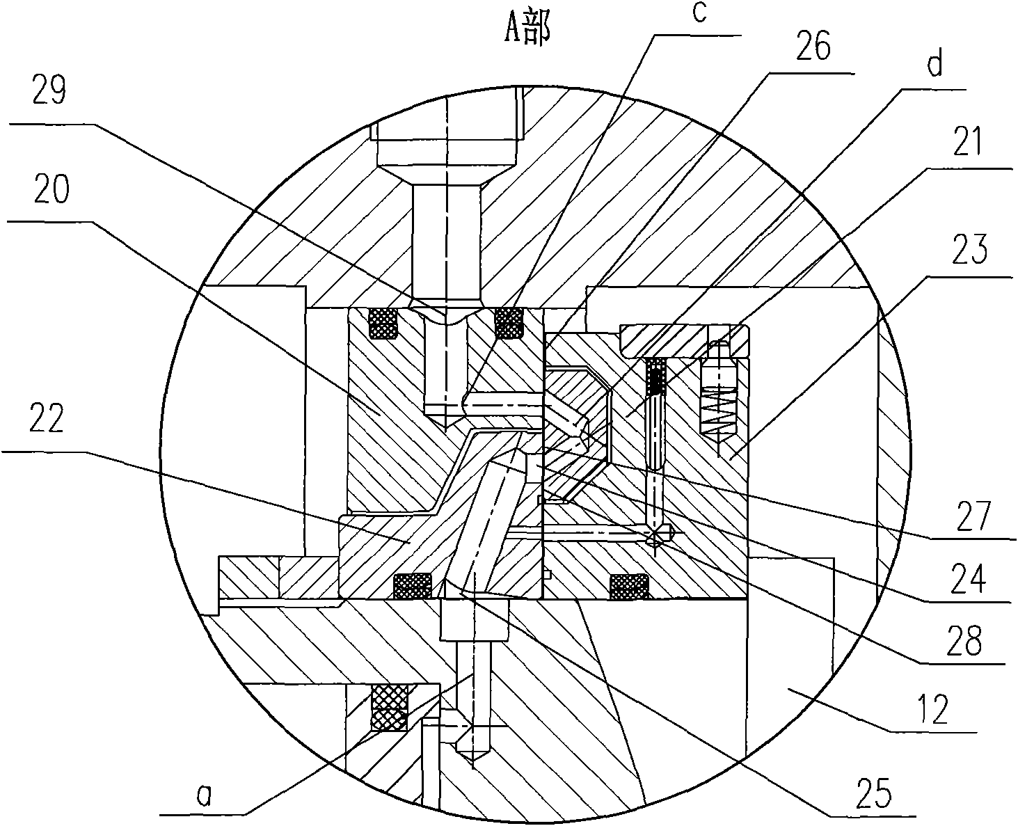
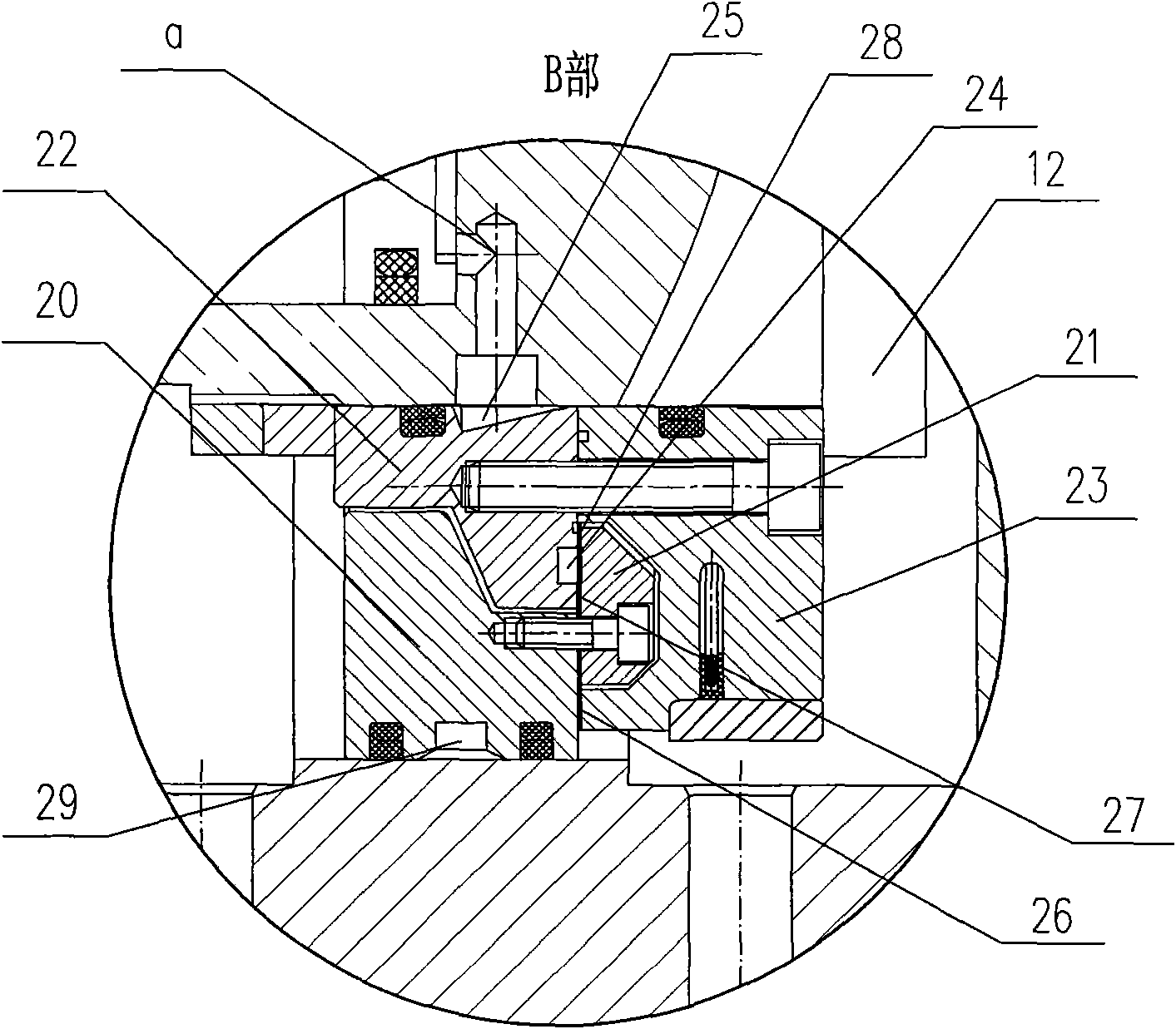
[0013] Specific implementation mode two: combination figure 2 and image 3 Describe this embodiment, the difference between this embodiment and the specific embodiment is that the hydraulic slip ring 2 is composed of a first component 20, a second component 21, a third component 22 and a fourth component 23; the first component 20 and the second component 21 are fixedly connected together, the third part 22 and the fourth part 23 are fixedly connected together, the second part 21 is embedded in the fourth part 23, an L-shaped through hole c is opened on the first part 20, the said first part There is an oil inlet ring groove 29 on the surface connecting the first part 20 and the housing, a V-shaped through hole d is opened on the second part 21, and a ring-shaped through hole d is opened on the connecting surface of the third part 22 and the second part 21. Groove 24, a tapered annular groove 25 is formed on the surface where the third part 22 is connected with the shaft 12,...

specific Embodiment approach 3

[0014] Specific implementation mode three: combination figure 2 and image 3 Describe this embodiment, the difference between this embodiment and the specific embodiment is that the gap between the first part 20 and the fourth part 23 is the first gap 26, and the annular groove between the second part 21 and the third part 22 The slits on both sides of 24 are respectively the second slit 27 and the third slit 28; the first slit 26, the second slit 27 and the third slit 28 are on the same plane, and the slit value of the three slits is h; The pressure oil between the slit 26, the second slit 27 and the third slit 28, and the pressure oil in the annular groove 24 respectively establish a pressure plane and a pressure area, thereby constituting a static pressure adjustment mechanism; the pressure oil passes through the through hole Transmission to the cylinder of the shaft 12; the first gap 26, the second gap 27 and the third gap 28 constitute three variable restrictors, and th...


PUM


Abstract

A rotary cylinder using a planar end oil film for sealing hydraulic slipring relates to the field of computer numerical control, and aims at the defect of low rotary speed of prior rotary cylinder. One end of shaft according to the invention is connected with a motor through a coupling. The end at the other end of shaft is provided with a cylinder. An opening is provided on the inner end plane of cylinder of shaft. One end of driving pin is matched with the opening on the inner end plane of cylinder of shaft through screw thread fit. The other end of driving pin is matched with an opening on the head end plane of piston through clearance fit. A cylinder cover is sleeved on the piston rod of piston and seals the cylinder of shaft. A spring is sleeved on the piston rod of piston and is supported between the cylinder cover and the end plane connected between the piston rod of piston and the head of piston. The shaft is fixedly connected with the casing through a bearing and a hydraulic slipring. The oil inlet opening of casing is communicated with the oil inlet opening of hydraulic slipspring. The oil outlet opening of hydraulic slipspring is communicated with the oil inlet opening of cylinder of shaft. The oil outlet opening of cylinder of shaft is communicated with the oil outlet opening of casing. The rotary cylinder according to the invention provides power for a power chuck and has the advantages of excellent reliability, simple structure and high rotary speed.

Description

technical field [0001] The invention relates to the technical field of numerical control machine tools, in particular to a rotary oil cylinder using the oil film sealing technology on the plane end face to provide power for a power chuck. Background technique [0002] End face seal is a kind of axial seal, also known as mechanical end face seal, referred to as mechanical seal, is the most important type of fluid mechanical rotary shaft seal, and is a commonly used rotary shaft seal. Compared with the gland soft packing seal, it has low leakage. , low friction and wear, long service life, reliable operation, no need for daily maintenance and other advantages, so it has been widely used in modern industrial production. [0003] With the advancement of science and technology and the development of production, various departments of the national economy require the machinery industry to continuously provide advanced technical equipment and develop new product varieties to meet t...

Claims


Application Information

Patent Timeline
IPC IPC(8): F15B15/14B23B31/30
Inventor 姜继海胡志栋
Owner 湖南哈工机器人研究院有限公司
Why Eureka
Try Eureka