Shaft sealing device for high-temperature pressure-proof star-type feeder

A shaft sealing and feeder technology, which is applied in the directions of engine sealing, combustion type, mechanical equipment, etc., can solve the problems of short service life of the shaft end sealing device, insufficient high temperature resistance and pressure resistance performance, etc.

Active Publication Date: 2009-10-07
BEIJING GUODIAN FUTONG SCI & TECH DEV +1
View PDF0 Cites 10 Cited by
  • Summary
  • Abstract
  • Description
  • Claims
  • Application Information

AI Technical Summary

Problems solved by technology

[0004] Therefore, the purpose of the present invention is to solve the problems of the prior art shaft en

Method used


Image

  • Shaft sealing device for high-temperature pressure-proof star-type feeder
  • Shaft sealing device for high-temperature pressure-proof star-type feeder

Examples


Embodiment Construction

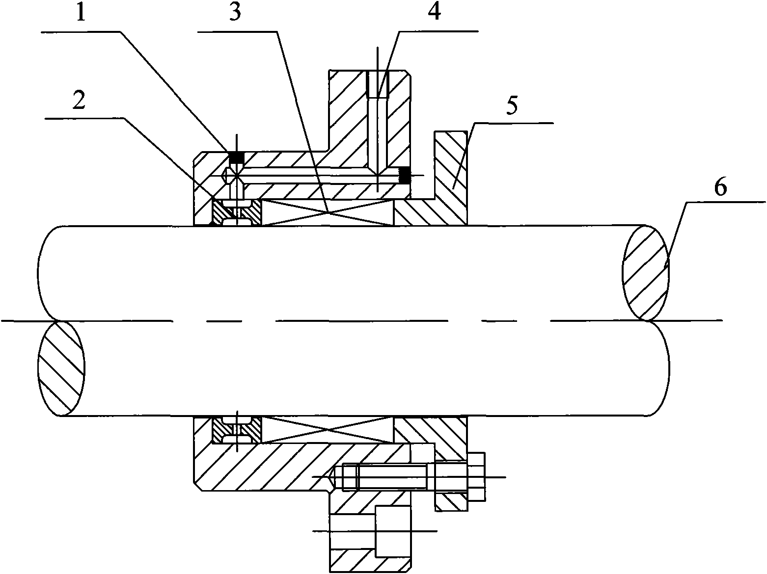
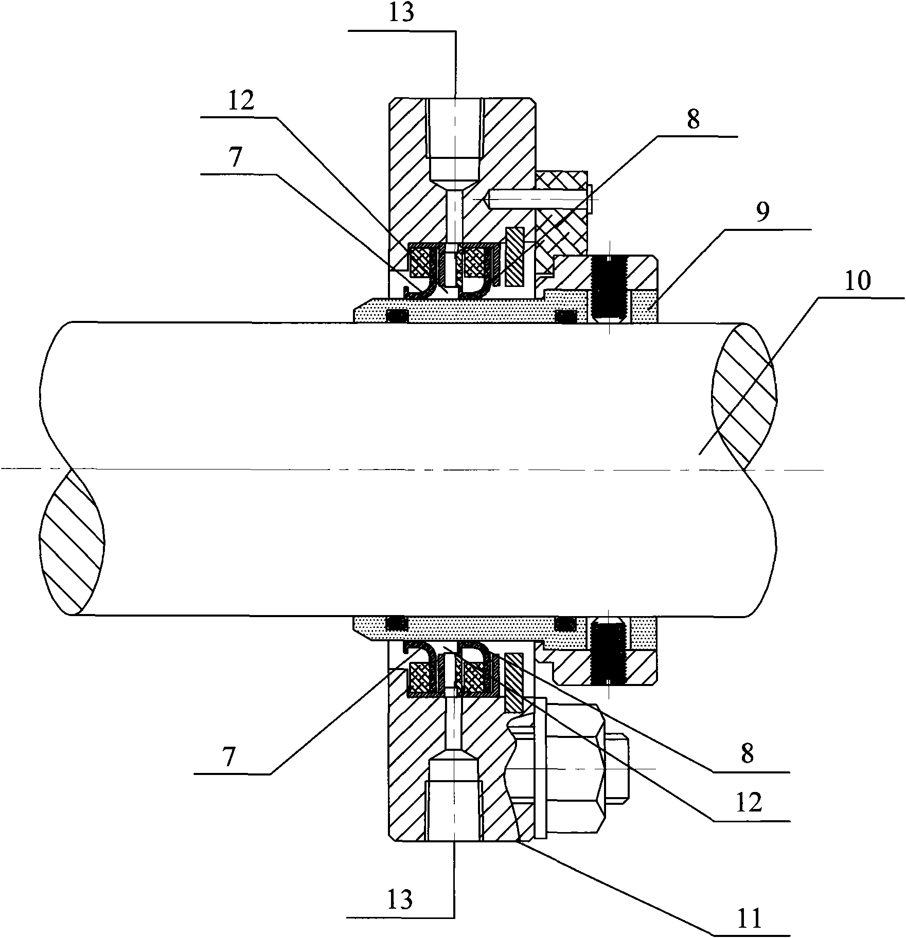
[0013] combine figure 1 It is a structural schematic diagram of the high-temperature and pressure-resistant star feeder shaft sealing device of the present invention, the rotating shaft 10 is the main transmission shaft, and the high-wear-resistant shaft sleeve 9 is installed on it, and the high-wear-resistant shaft sleeve 9 is made of high-wear-resistant alloy material Manufactured, for example, it can be silicon carbide composite SS316L, the shaft 10 and the shaft sleeve 9 are sealed by an O-ring, and there are two seals on the shaft sleeve 9: the first lip seal 7 and the second lip seal 8, which are connected to the shaft The seal of the sleeve 9 is a dynamic seal, and two air-tight holes 13 are provided between the first lip seal 7 and the second lip seal 8 .

[0014] In the pneumatic slag conveying system, the inlet of the feeder using this device is installed at the outlet of the conveying tank, and the conveying pipeline is installed under the outlet. The actual temper...


PUM


Abstract

The present invention provides a shaft sealing device for high-temperature pressure-proof star-type feeder, which applies mechanical sealing to combine with gas sealing phase, including a rotation shaft 4, high abrasion-proof shaft sleeve 3, a first lip seal 1, a second lip sealing 2 and a body case 5, in pneumatic conveying device of dry granular medium, the invention provided technical scheme can assure to prolong service life of the shaft end sealing device and improve its performance at a certain pressure (0.6 MPa) and temperature (maximum 300DEG).

Description

technical field [0001] The invention belongs to the field of pneumatic conveying of powdery or granular materials, in particular to a shaft sealing device of a high-temperature and pressure-resistant star feeder. Background technique [0002] Boiler bottom slag (dry slag) in the electric power industry is crushed by a steel belt conveyor and a secondary slag crusher, and the particle size is controlled within 5mm. In the slag bin at the end. Due to the large material size and poor fluidity of the slag, when there is too much slag entering the pipeline instantaneously, it will cause difficulty in transportation. Therefore, a star feeder is installed at the discharge port of the conveying device (that is, the entrance of the conveying pipeline) to realize Feed evenly. The operating temperature of the conveyed slag medium is about 300 degrees, the highest impact temperature can reach about 350 degrees instantaneously, and the maximum medium pressure can reach about 0.6MPa. S...

Claims


Application Information

Patent Timeline
IPC IPC(8): F16J15/32F16J15/40F23C10/24F23J1/00F16J15/3232
Inventor 董启强李新生张轲轲刘新华丁岩峰周靖
Owner BEIJING GUODIAN FUTONG SCI & TECH DEV
Why Eureka
Try Eureka