Temperature control method for projection objective of photoetching machine

A temperature control method and technology of projection objective lens, which are applied in the direction of using electric method for temperature control, electrical program control, microlithography exposure equipment, etc., can solve the problems of increasing system stabilization time and long search process, etc.

Active Publication Date: 2009-10-07
SHANGHAI MICRO ELECTRONICS EQUIP (GRP) CO LTD +1
View PDF0 Cites 18 Cited by
  • Summary
  • Abstract
  • Description
  • Claims
  • Application Information

AI Technical Summary

Problems solved by technology

The process of finding the optimal water temperature in this alg

Method used


Image

  • Temperature control method for projection objective of photoetching machine
  • Temperature control method for projection objective of photoetching machine
  • Temperature control method for projection objective of photoetching machine

Examples


Embodiment approach

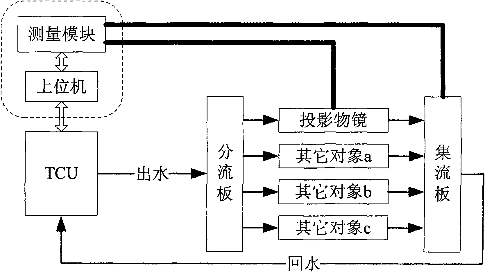
[0042] Such as figure 1 In the objective lens temperature control system shown, the TCU receives the set value sent by the controller module, and controls the internal heater and refrigerator according to a certain algorithm, thereby controlling the temperature of the circulating fluid to be close to the set value. The circulating fluid provided by the TCU is divided into multiple branches through the shunt, flows through the projection objective lens and other object components, and finally is combined by the current collector to flow back to the TCU.

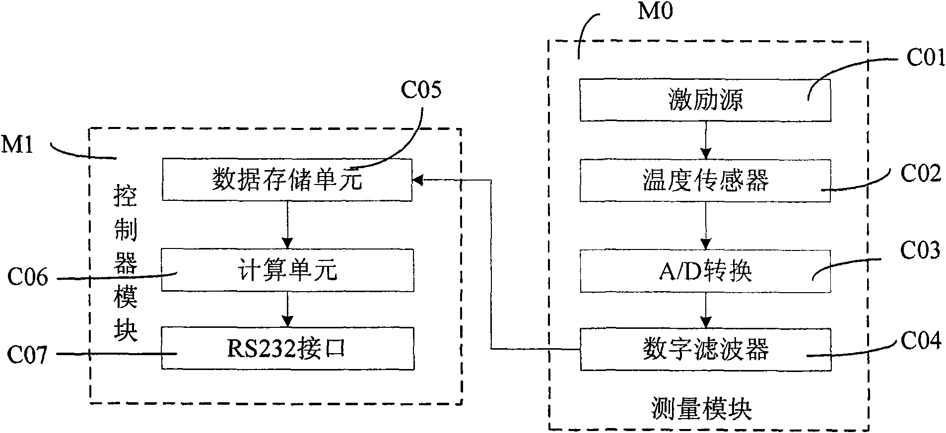
[0043] The invention provides a temperature control device, which mainly includes a measurement module M0 and a controller module M1.

[0044] Such as figure 2 As shown, the present invention provides a temperature control device for sending commands to the TCU, which includes a temperature measurement module M0 and a controller module M1, and the temperature measurement module M0 includes an excitation source C01, a sensor ...


PUM


Abstract

The invention provides a temperature control method for a projection objective of a photoetching machine, where the objective temperature is regulated to a set value of the objective temperature by use of a temperature control unit (TCU), comprising the following control steps: initializing system parameters, deciding to enter which control step: pre-regulating the TCU inner water temperature to a set value; using switch control, with the objective temperature as a master control variant, controlling the objective temperature in a target accuracy of step P2; using a cascade control arithmetic with a Smith predictor, with the objective temperature as the master control variant, using an increment PID arithmetic, and a water temperature at a flow plate as a secondary control variant, using an increment PI arithmetic for the secondary control loop; using a cascade control arithmetic without a Smith predictor, with the objective temperature as a master control variant, using an increment PI arithmetic for the master control loop, and the water temperature at the flow plate as a secondary control variant, using the increment PI arithmetic for the secondary control loop; using the increment PI arithmetic, where the control variant is the water temperature at the flow plate.

Description

technical field [0001] The invention belongs to the field of temperature control of components, and relates to a method for controlling the temperature of a projection objective lens of a photolithography machine. Background technique [0002] In the semiconductor industry, constant temperature control is required for certain critical components, such as projection objectives in photolithography machines. Due to the narrow working space of these key parts, strict requirements on the working environment and high temperature control accuracy, they cannot be directly controlled by ordinary temperature control equipment such as fans, electric heaters, and air conditioners. [0003] At present, special equipment is generally used in the industry to control the temperature of key parts by providing temperature-controlled circulating fluid to exchange heat with key parts. [0004] In the projection objective lens temperature control system, the device that provides this temperatur...

Claims


Application Information

Patent Timeline
IPC IPC(8): G03F7/20G05D23/19G05B19/04
Inventor 金敏李小平聂宏飞汤勇余小虎黄友任于文忠罗晋
Owner SHANGHAI MICRO ELECTRONICS EQUIP (GRP) CO LTD
Why Eureka
Try Eureka