
Acceleration and deceleration control method of mechanical movable parts

A technology of acceleration and deceleration control and drive control, applied in the direction of digital control, electrical program control, etc., can solve the problems of increased speed, large speed change, and large acceleration of the movable part

Active Publication Date: 2011-12-07
FANUC LTD
View PDF2 Cites 0 Cited by
  • Summary
  • Abstract
  • Description
  • Claims
  • Application Information

AI Technical Summary

Problems solved by technology

However, there is a problem that the speed fluctuation of the movable part increases depending on the position of the speed amplifying mechanism. Even if the rotation speed of the motor is constant, the speed of the movable part increases sharply or decreases sharply depending on the position of the speed amplifying mechanism, and the speed fluctuates. large, large acceleration occurs

Method used

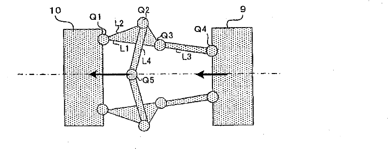
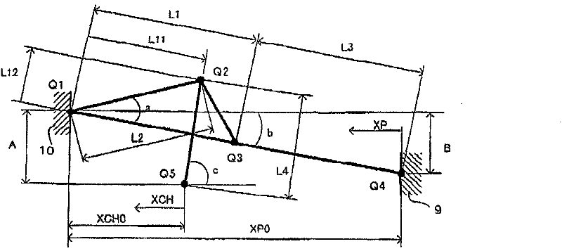

Image

  • Acceleration and deceleration control method of mechanical movable parts
  • Acceleration and deceleration control method of mechanical movable parts
  • Acceleration and deceleration control method of mechanical movable parts

Examples


Embodiment Construction

[0027] Next, an example of applying the acceleration / deceleration control method of the mechanical movable part of the present invention to the drive control of the movable platen (movable part) of the electric injection molding machine will be described.

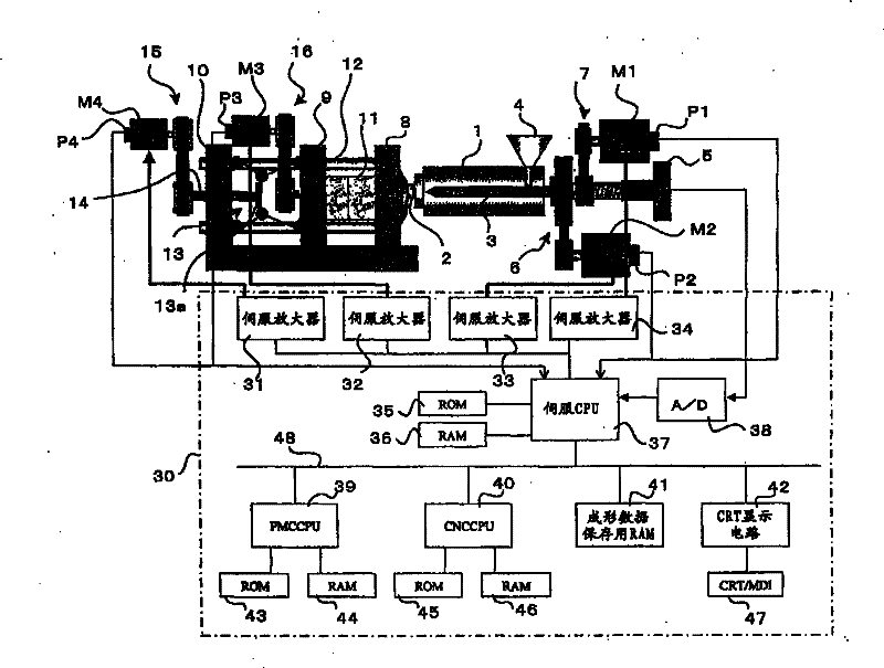
[0028] figure 1 It is a schematic diagram of an example of an electric injection molding machine to which the acceleration / deceleration control method of the present invention is applied.

[0029] A nozzle 2 is mounted on the tip of the injection cylinder 1 . Insert the injection screw 3 into the injection cylinder 1 . The injection screw 3 is provided with a pressure sensor 5 such as a load cell for detecting the resin pressure from the pressure applied to the injection screw 3 . The injection screw 3 is rotated by a servomotor M2 for rotation through a transmission mechanism 6 composed of a pulley, a belt, and the like. In addition, the injection screw 3 is driven by the injection servo motor M1 through the transmissio...


PUM


Abstract

The invention provides an acceleration and deceleration control method of a mechanical movable part. In driving and controlling the movable part of the machine through the servo motor according to the movement command from the control device, and controlling the position and speed of the movable part, the acceleration corresponding to the position of the servo motor during the movement to the target position based on the movement command is taken as The acceleration mode is preset in the control unit. Then, during driving of the servo motor, an acceleration corresponding to the position of the servo motor is given according to this acceleration pattern.

Description

technical field [0001] The present invention relates to an acceleration / deceleration control method of a movable part of a machine whose position and speed are controlled by a servo motor. Background technique [0002] In various machines such as industrial machines, the position and speed of the movable part are controlled by driving the movable part of the machine with a servo motor and controlling the position and speed of the servo motor. [0003] In the control of the position and speed of the movable part, a control device such as a numerical controller performs acceleration and deceleration control based on the moving distance from the start point to the end point of the movable part and the set speed to generate The generated movement command is used to drive the servo motor to drive and control the movable part. In this acceleration / deceleration control, generally, the speed is accelerated to the set speed according to the set time constant, and deceleration is sto...

Claims


Application Information

Patent Timeline
Patent Type & Authority Patents(China)
IPC IPC(8): G05B19/416
Inventor 高次聪内山辰宏渡边广小林稔丸山淳平
Owner FANUC LTD
Learn More