
Energy-saving magnetic shielding transformer

A magnetic shielding and energy-saving technology, applied in the field of transformers, can solve the problems of local overheating of upper and lower clamps, and achieve the effects of low manufacturing cost, obvious energy-saving effect and convenient processing.

Inactive Publication Date: 2009-10-07
江苏波瑞电气有限公司
View PDF0 Cites 3 Cited by
  • Summary
  • Abstract
  • Description
  • Claims
  • Application Information

AI Technical Summary

Problems solved by technology

[0003] In order to overcome the narrow gaps in the upper and lower clamps in the prior art which are only suitable for small power transformers and cannot completely solve the technical problem of local overheating of the upper and lower clamps, the purpose of the present invention is to provide a simple process and low cost that can effectively reduce Eddy current formation on the upper and lower clamps, energy saving and consumption reduction, energy-saving magnetic shielding transformer with wide applicability

Method used


Image

  • Energy-saving magnetic shielding transformer
  • Energy-saving magnetic shielding transformer
  • Energy-saving magnetic shielding transformer

Examples


Embodiment Construction

[0011] The present invention will be described in detail below in conjunction with the accompanying drawings and embodiments.

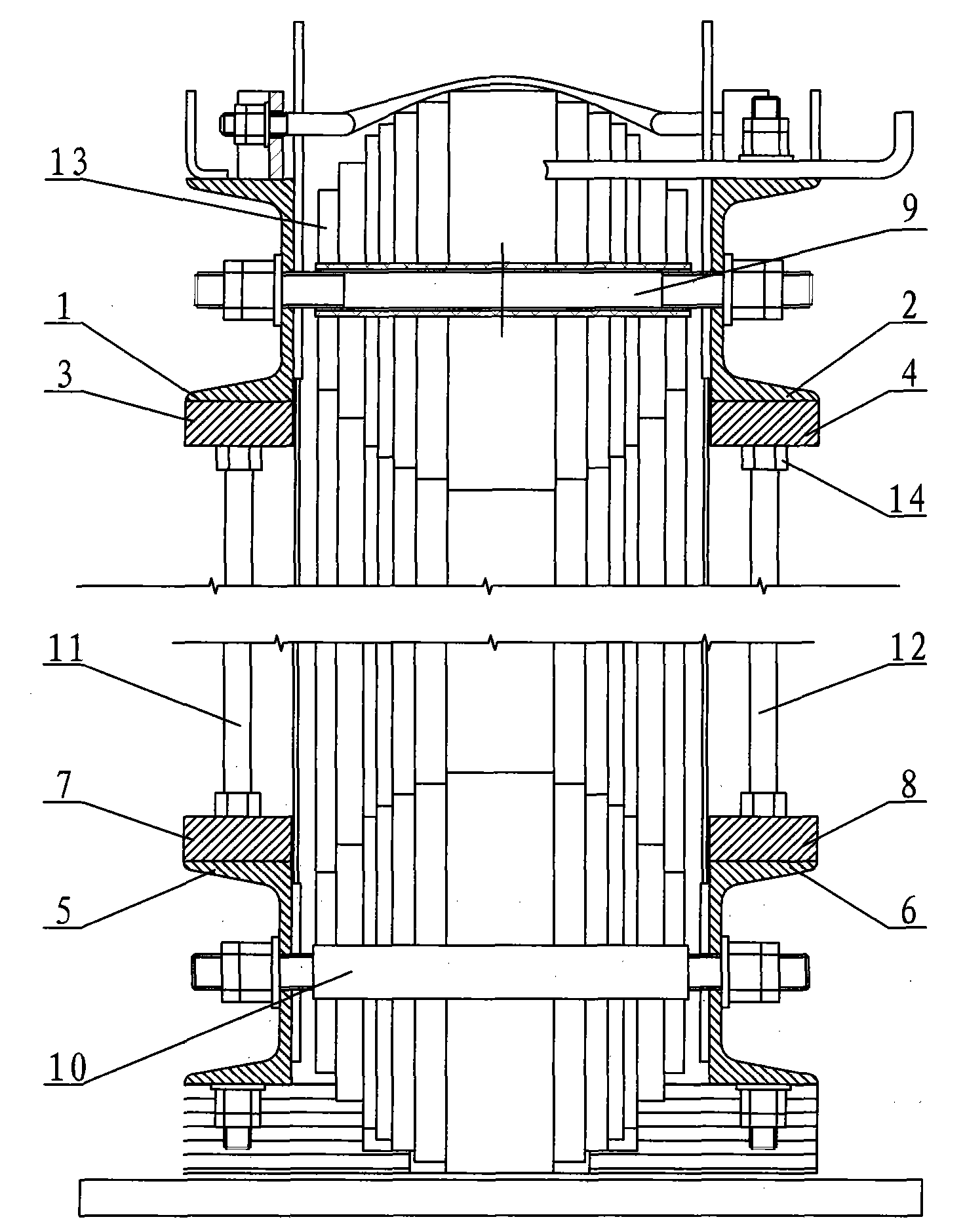
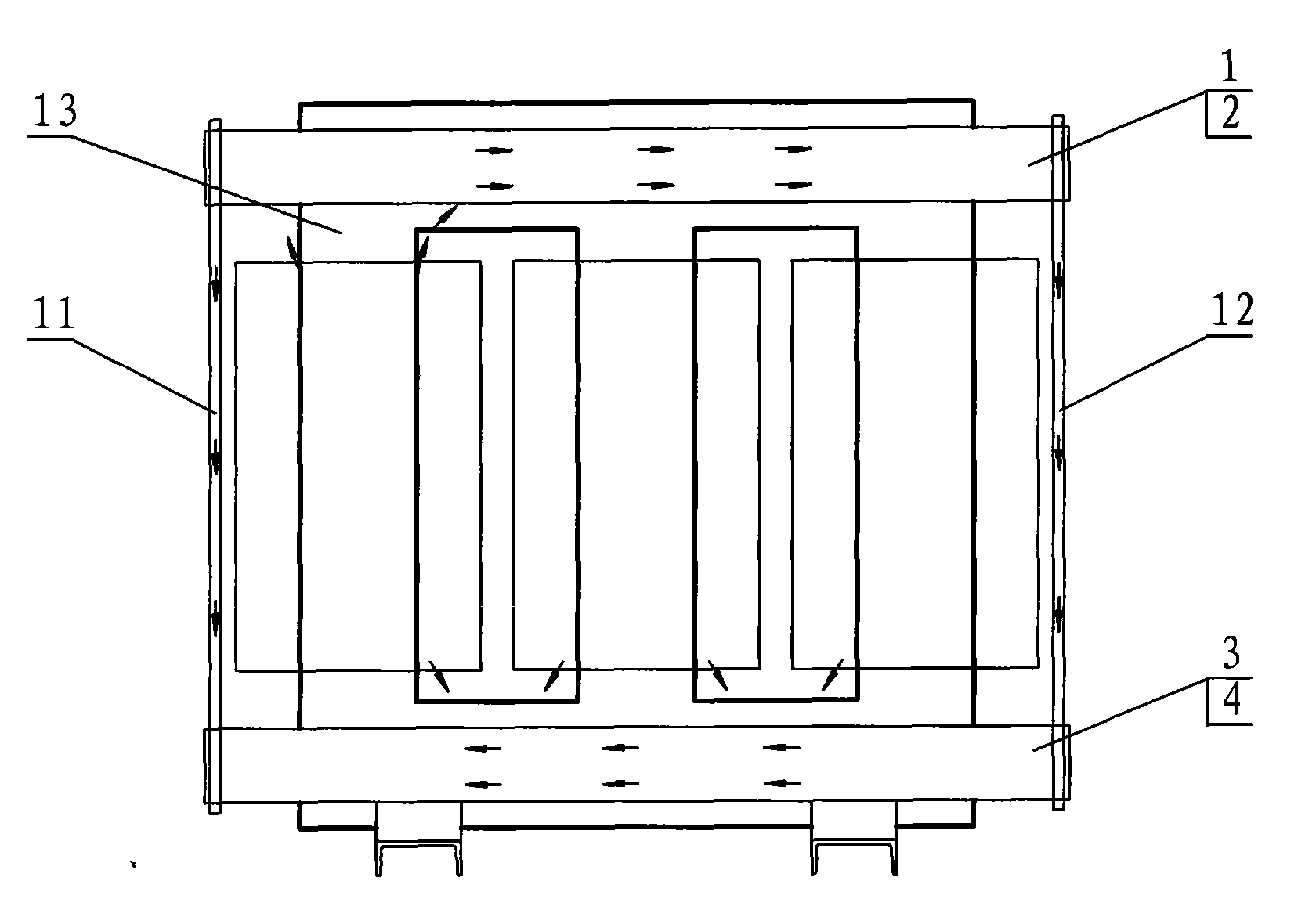
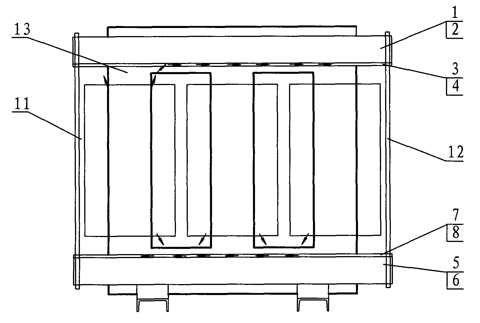
[0012] figure 1 Among them, two upper clamps 1, 2 and two lower clamps 5, 6 tighten the iron core 13 into a steel body through the horizontal tie rods 9, 10, and the upper clamp 1 and the lower clamp 5 are locked through the vertical tie rod 11 , the upper clamp 2 and the lower clamp 6 are locked by the vertical pull rod 12, and the two upper clamps 1, 2 and the two lower clamps 5, 6 are respectively provided with an upper shielding layer 3, 4 and a lower shielding layer on the side close to the coil Layers 7 and 8, the upper shielding layers 3 and 4 are locked on the bottom surfaces of the two upper clamps 1 and 2 through nuts 14, and the lower shielding layers 7 and 8 are locked on the bottom surfaces of the two lower clamps 5 and 6 through nuts 14. top surface.

[0013] After the main magnetic flux and part of the leakage flux are generated in th...


PUM


Abstract

The invention relates to an energy-saving magnetic shielding transformer comprising two upper clamping pieces, two lower clamping pieces and an iron core; the two upper clamping pieces and the two lower clamping pieces are respectively locked by a transverse pull rod for tightening the iron core into a steel body; the space between the two upper clamping pieces and the two lower clamping pieces is locked by a vertical pull rod; the bottom surfaces of the two upper clamping pieces and the top surfaces of the two lower clamping pieces are respectively provided with upper shielding layers and lower shielding layers, which cause the original leakage magnetic field to be cut off by the shielding layers and lead the leakage magnetic flux entering into the upper clamping pieces and the lower clamping pieces to be reduced, thereby effectively reducing the vortex formation on the upper clamping pieces and the lower clamping pieces, lowering the additional loss and achieving the purpose of energy conservation and consumption reduction.

Description

technical field [0001] The invention relates to a transformer, in particular to an energy-saving magnetic shielding transformer. Background technique [0002] When the transformer is working, in addition to the main magnetic flux guided in the iron core, there is also a leakage flux formed by the external connection of conductive parts. The leakage flux causes eddy currents to be generated on the upper and lower clamps outside the iron core, and the eddy currents will cause the upper and lower Clamp local high temperature overheating. In order to reduce the leakage flux, one of the measures taken at present is to separate the bottom edge of the upper and lower clamps near the coil with a narrow slit with a smaller width. This can reduce power loss, but there are still gaps in the upper and lower clamps. Leakage flux, for high-power transformers, cannot prevent local overheating, and the reduction of power loss is not obvious; the other is a layered shielding device inside t...

Claims


Application Information

Patent Timeline
Patent Type & Authority Applications(China)
IPC IPC(8): H01F27/36
Inventor 朱文堂戴宪生蒋柏华王新兵
Owner 江苏波瑞电气有限公司
Learn More