Installation method for rubber intermediate head of high voltage power cable and device

An intermediate joint, high-voltage power technology, used in cable installation devices, cable joints, cable installation and other directions, can solve the problems of difficult cable installation, time-consuming and laborious, and large contact surface between the joint cavity and the cable, saving time for installation. Effort-saving, simple and reliable operation, and shortened set-up time

Active Publication Date: 2009-10-07
WUHAN NARI LIABILITY OF STATE GRID ELECTRIC POWER RES INST
View PDF1 Cites 5 Cited by
  • Summary
  • Abstract
  • Description
  • Claims
  • Application Information

AI Technical Summary

Problems solved by technology

[0002] High-voltage power cable rubber intermediate joints have the advantages of safety, reliability, simple installation, and practicality. It is easy to form a vacuum and cannot move, which brings certain difficulties to the cable installation. In the past, when installing 110kV power cables, manual guide chains were used to force the joints into the cables, or pre-expanded and braced tubes were used. These methods were time-consuming It is laborious, and it is easy to cause damage to the cable main body and connectors, leaving hidden dangers of accidents
In recent years, there has been a relatively advanced installation method and device for cable accessories on the market, such as the "Rubber Power Cable Accessory Installation Method and Device" disclosed in Chinese Patent Application No. 200410022854.6. This method and device can make high-voltage power cable terminals The installation is fast and will not leave indentations, scratches, etc. on the main part of the cable, but this method and device are only suitable for the installation of power cable terminals, not suitable for the installation of power cable intermediate joints

Method used


Image

  • Installation method for rubber intermediate head of high voltage power cable and device
  • Installation method for rubber intermediate head of high voltage power cable and device

Examples


Embodiment Construction

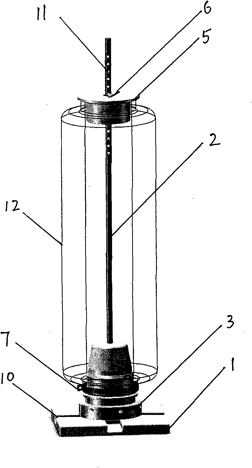
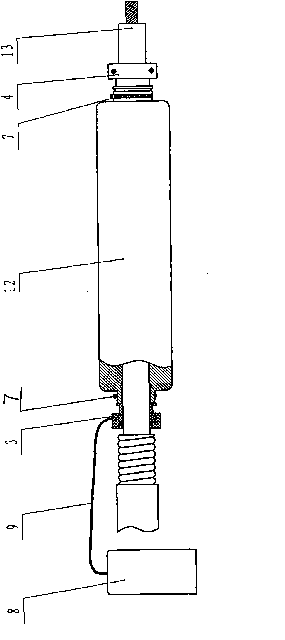
[0012] exist figure 1 Among them, before the intermediate connector is inserted into the cable, the method of inserting the half sleeve into the intermediate joint is used, and two pairs of half sleeves are respectively inserted into the inner cavities at both ends of the intermediate joint. First, on the base 1 with a hollow cone, put a A metal rod 2 that is longer than the intermediate joint 12 is fixed to the cone. There are many bolt holes 11 on the metal rod 2. The outer diameter of the cone is slightly smaller than the inner diameter of the half sleeve. A pair of half sleeves 3 with sealing rings are placed on the cone. Fix the bottom of the body with screws, and apply grease on the part of the half sleeve 3 that will be inserted into the intermediate joint, then put the intermediate joint 12 on the metal rod 2 and the half sleeve 3, insert the baffle plate 5 into the metal rod 2 and In contact with the other end of the joint 12, insert the pin 6 into the fastening hole ...


PUM


Abstract

The invention discloses an installation method for rubber intermediate head of high voltage power cable and a device, comprising the following steps: sleeving the intermediate head in cable main insulation in a certain depth, aerating high pressure gas in the chamber of the intermediate head and surface of cable main insulation, stopping aeration when moving in the given position; before sleeving the intermediate head in the cable, adopting the method for sleeving intermediate head using Half sleeve, namely, sleeving two Half sleeves into the chamber at two ends of the intermediate head, then sleeving the intermediate head with two ends having the Half sleeves into the cable main insulation using the high pressure gas, the fore end of Half sleeve having sealing ring and aerating hole; after connecting two cables, restarting to aerate, then pushing the intermediate head in the opposite direction to move in the given position to stop aeration, then unloading two Half sleeves, and the intermediate head elastically enclasping in the cable main body. The invention greatly improves the installation efficiency of the intermediate head and has simple and reliable operation, in particular is applicable to the installation of 100KV power cable.

Description

technical field [0001] The invention belongs to the technical field of installing high-voltage cable accessories, and relates to a method and a device for installing a rubber intermediate joint of a high-voltage power cable. Background technique [0002] High-voltage power cable rubber intermediate joints have the advantages of safety, reliability, simple installation, and practicality. It is easy to form a vacuum and cannot move, which brings certain difficulties to the cable installation. In the past, when installing 110kV power cables, manual guide chains were used to force the joints into the cables, or pre-expanded and braced tubes were used. These methods were time-consuming It is laborious, and it is easy to cause damage to the cable main body and joints, leaving hidden dangers of accidents. In recent years, there has been a relatively advanced installation method and device for cable accessories on the market, such as the "Rubber Power Cable Accessory Installation M...

Claims


Application Information

Patent Timeline
Patent Type & Authority Applications(China)
IPC IPC(8): H02G1/00H02G15/18H02G15/08
Inventor 王宇莫青赵森王伟李忠群
Owner WUHAN NARI LIABILITY OF STATE GRID ELECTRIC POWER RES INST
Why Eureka
Try Eureka