Method for controlling automatic operation of standby power by microcomputer of inner bridge and single bus connection

A backup power supply and control method technology, applied in the direction of emergency power supply arrangements, electrical components, circuit devices, etc., can solve problems such as large limitations in operation mode, poor adaptability, and complex action principles

Active Publication Date: 2009-10-07
STATE GRID JIANGSU ELECTRIC POWER CO ZHENJIANG POWER SUPPLY CO +1
View PDF0 Cites 25 Cited by
  • Summary
  • Abstract
  • Description
  • Claims
  • Application Information

AI Technical Summary

Problems solved by technology

[0003] Most of the control methods adopted by the automatic input device are designed according to the action flow proposed by people, which do not fully conform to the basic principle of automatic input of the backup power supply. Compared with the electromagnetic equipment, its operation principle is complicated and the operation mode is limited. On the contrary, it loses the advantages that the microcomputer equipment self-injection should have
In particular, the existing microcomputer-controlled backup power automatic input device has poor adaptability when it is connected to a local power plant. Since the protection lock is not separated, when a main transformer fai

Method used


Image

  • Method for controlling automatic operation of standby power by microcomputer of inner bridge and single bus connection
  • Method for controlling automatic operation of standby power by microcomputer of inner bridge and single bus connection
  • Method for controlling automatic operation of standby power by microcomputer of inner bridge and single bus connection

Examples


Embodiment Construction

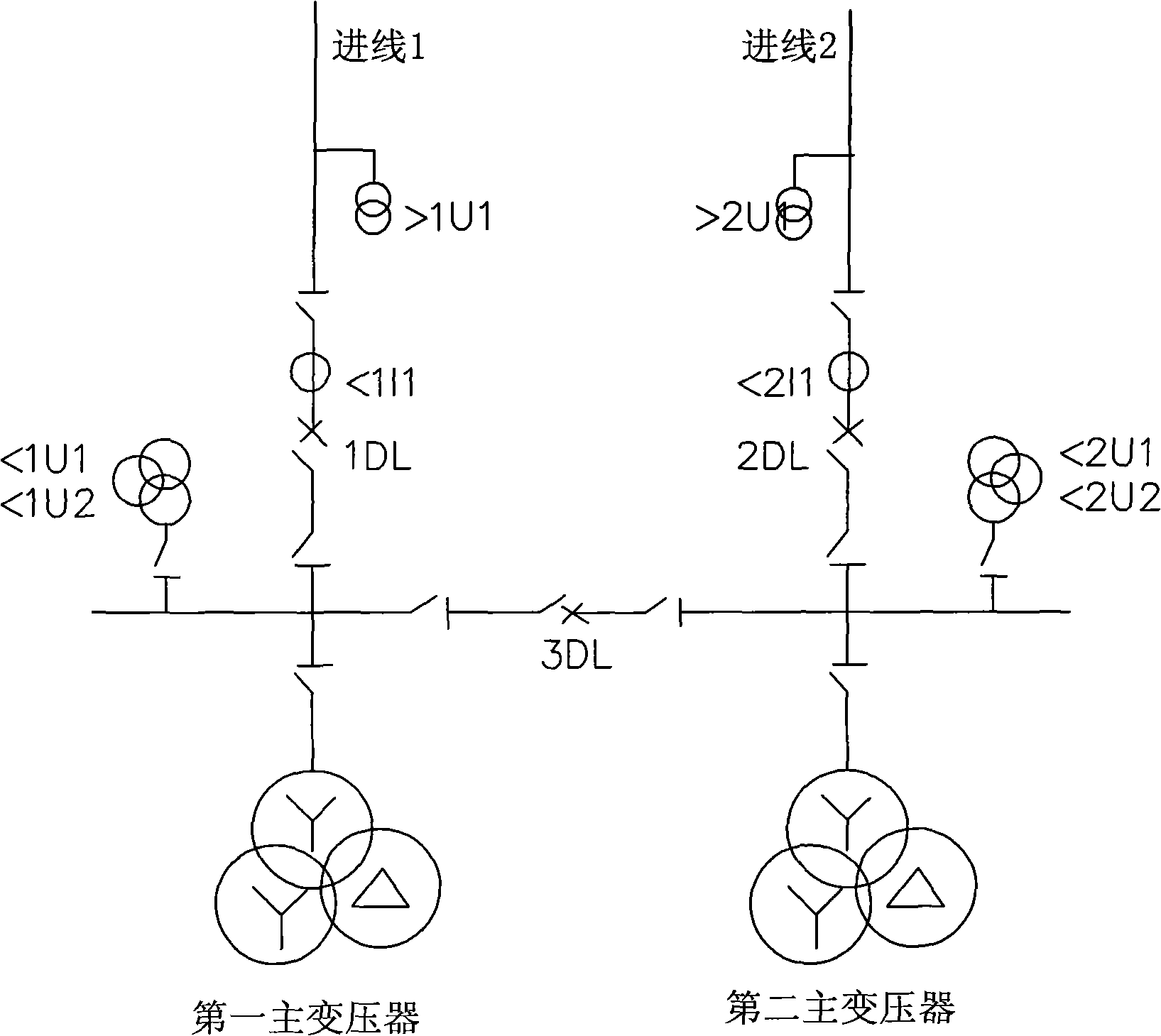
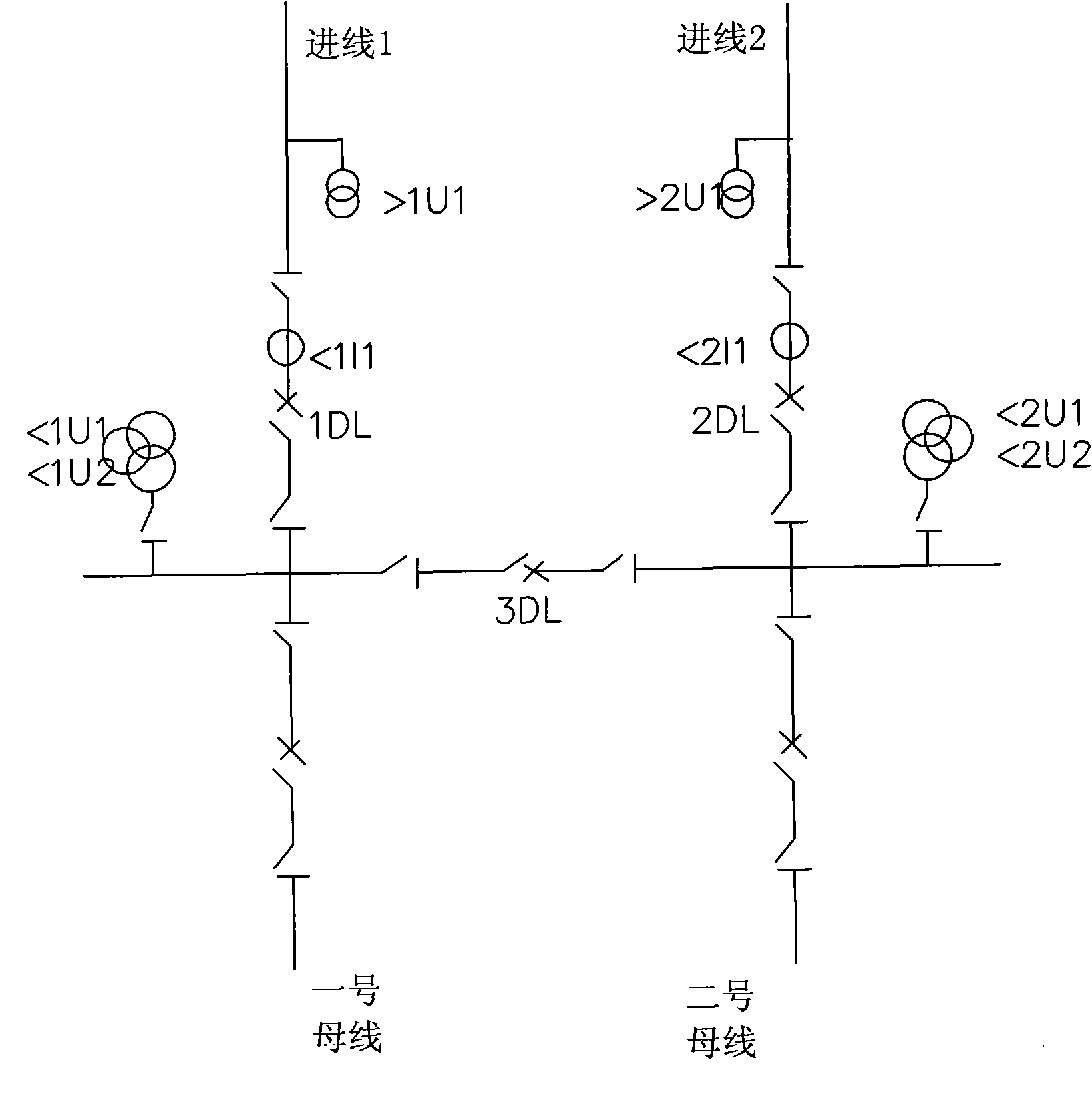
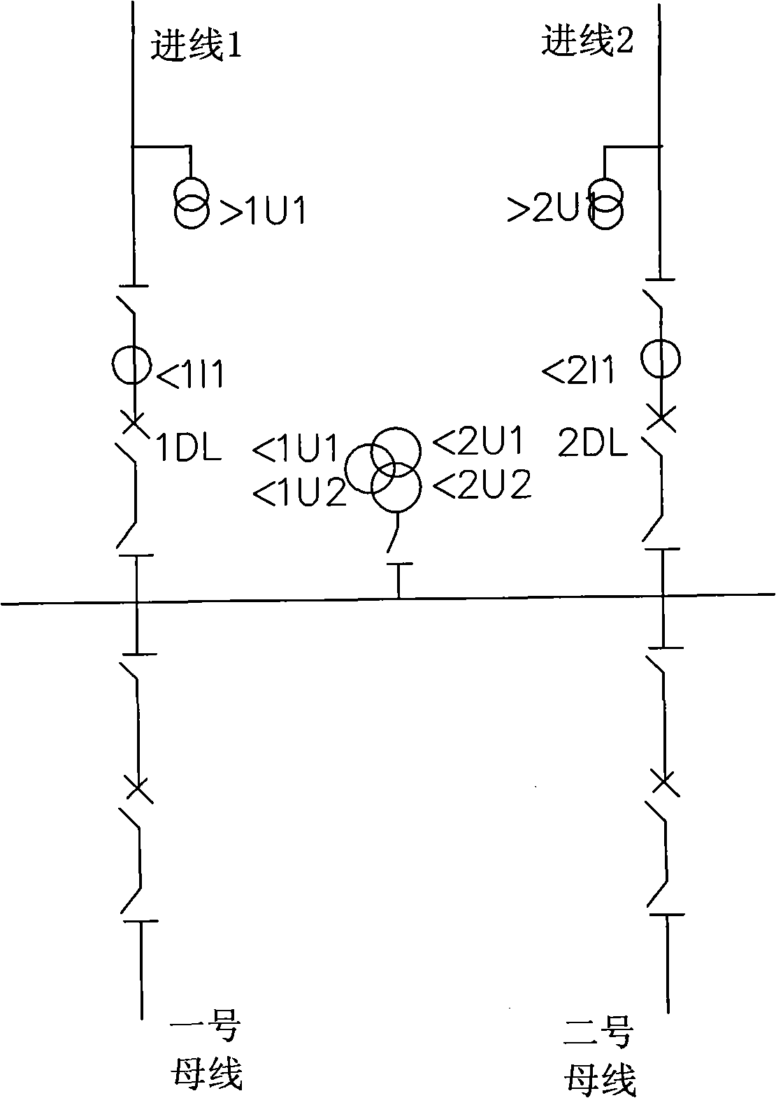
[0212] (1) Specific implementation methods of inner bridge wiring or single bus section wiring

[0213] Such as figure 1 or figure 2 As shown, the power transmission and distribution network applied in the method of the present invention includes two power supplies, the two power supplies are respectively connected in series with a circuit breaker 1DL and a circuit breaker 2DL, and are also connected with two main transformers (i.e. the first main transformer and the second main transformer) or two busbars (the busbar has two main transformers or load outlets), there is a circuit breaker 3DL between the two power sources, that is, inner bridge wiring or single busbar segment wiring, the high voltage side of the main transformer or the busbar. There are also voltage transformers on the line side of the voltage transformer and the power incoming line. Provide below the embodiment of the various inner bridge wirings or single bus segment wiring forms that are applied to the a...


PUM


Abstract

The invention belongs to control technology of electric power transmission and distribution, and relates to a method for controlling the automatic operation of standby power by using a microcomputer. The method includes two basic control methods which are the inner bridge connection or single bus sectional connection control method and the single bus connection control method, wherein the inner bridge connection or single bus sectional connection control method comprises the following control processes of: tripping control of a first breaker 1DL, tripping control of a second breaker 2DL, switching-on charge and discharge control of the first breaker 1DL, switching-on control of the first breaker 1DL, switching-on charge and discharge control of the second breaker 2DL, switching-on control of the second breaker 2DL, switching-on charge and discharge control of a third breaker 3DL, switching-on control of the third breaker 3DL, and abnormal signal control. The method has simple action principle and high reliability, is completely in accordance with the fundamental principle of the automatic operation of the standby power, and is applicable to the one-time main connection of electric power substations in three forms of inner bridge connection, single bus sectional connection and single bus connection, in the power transmission and distribution network.

Description

technical field [0001] The invention belongs to the control technology of electric power transmission and distribution, and relates to a method for using a microcomputer to control the automatic input of a backup power supply. Background technique [0002] At present, there are two types of automatic input devices for backup power in substations: electromagnetic and microcomputer. The electromagnetic backup power automatic input device needs to control the backup power automatic input process through a large number of relays and other mechanical and electrical devices, which occupies a large space, high equipment cost, troublesome maintenance, and is difficult to realize remote control. The microcomputer-controlled backup power automatic input device controls the automatic input process of the backup power through a microcomputer program, which has low cost and is easy to realize remote control. But the existing microcomputer controls the backup power supply [0003] Most ...

Claims


Application Information

Patent Timeline
IPC IPC(8): H02J9/06
CPCY02B70/30Y04S20/20
Inventor 汤大海
Owner STATE GRID JIANGSU ELECTRIC POWER CO ZHENJIANG POWER SUPPLY CO
Why Eureka
Try Eureka