Vehicular door-hinge device with checker
A technology of door hinges and lockers, which is applied to vehicle components, doors, transportation and packaging, etc., can solve problems such as the disappearance of the locking function of the stop roller and the wear and tear of the stop roller and the coil spring, so as to improve reliability and enhance The effect of engagement force
- Summary
- Abstract
- Description
- Claims
- Application Information
AI Technical Summary
Problems solved by technology
Method used
Image
Examples
no. 1 example
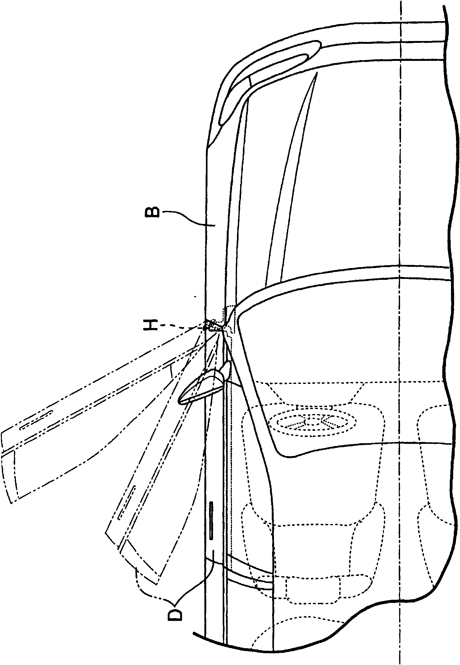
[0046] First, the description will start with the first embodiment of the present invention. exist figure 1 In the vehicle body B of the motor vehicle, a door D for opening and closing an entrance is rotatably attached via a door hinge H.
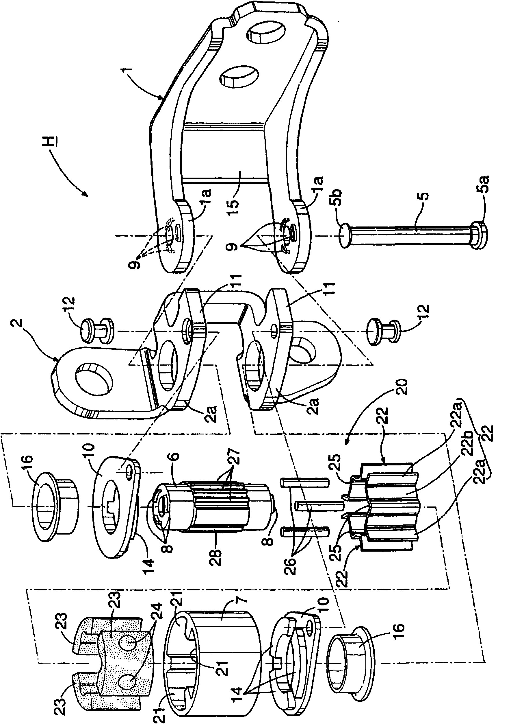
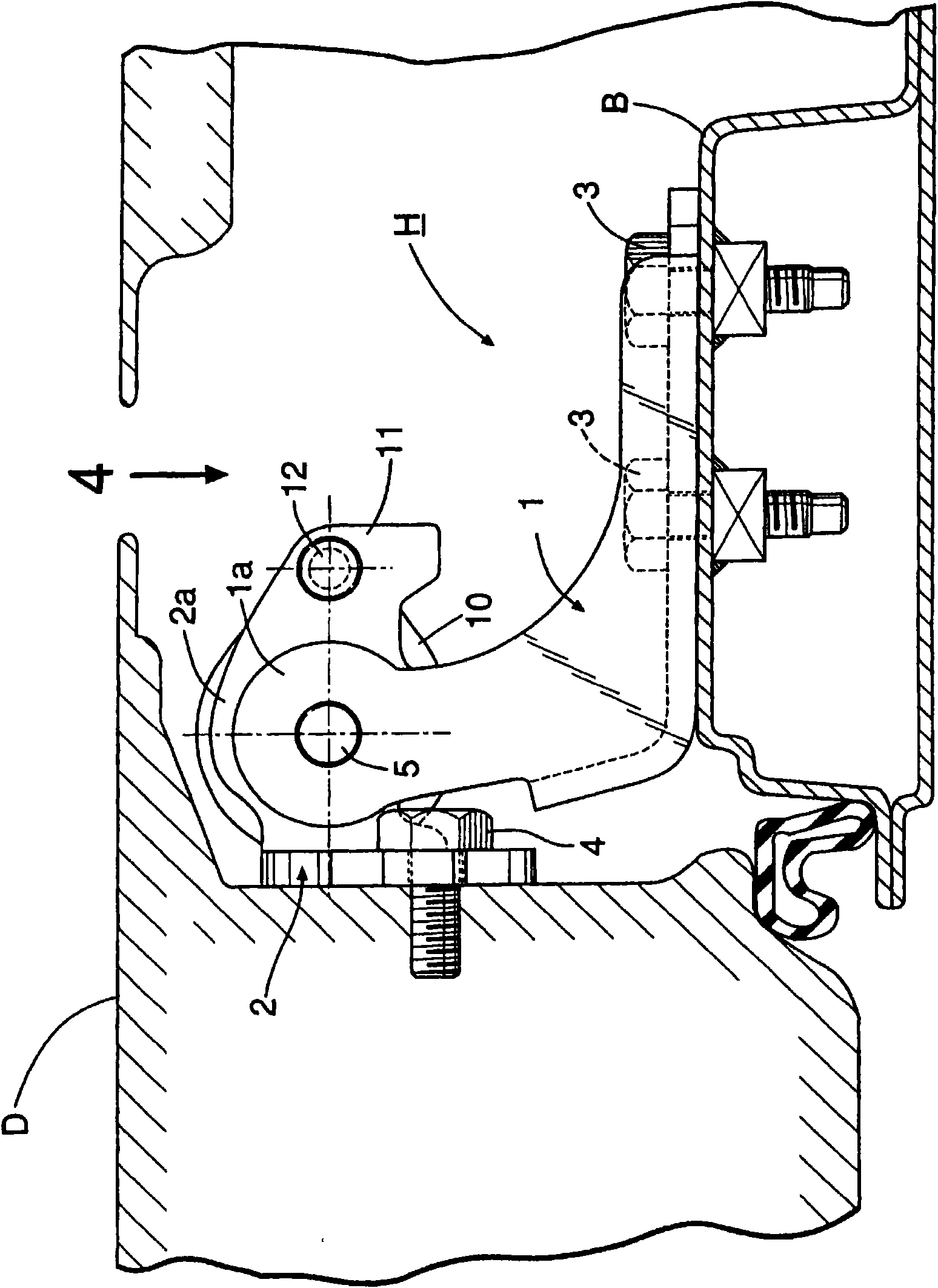
[0047] Such as Figure 2 to Figure 5 As shown, each door hinge H is composed of the following components: an inclusive bracket 1, which is fastened on the vehicle body B by a plurality of bolts 3; a plug-in bracket 2, which is fastened on the door D by a plurality of bolts 4; And the hinge pin 5 arranged in the vertical direction, which connects the two brackets 1, 2 so as to be relatively rotatable.
[0048] The inclusive bracket 1 has a pair of upper and lower inclusive arm parts 1a, and the upper and lower pair of inclusive arm parts 2a, 2a of the plug-in bracket 2 are arranged adjacent to the inner side of the pair of inclusive arm parts 1a respectively, and the hinge pin 5 It is arranged so as to penetrate these arm parts in the ver...
no. 2 example
[0069] next, yes Figure 9 A second embodiment of the invention is shown for illustration.
[0070] This second embodiment differs from the previous embodiment in the following respects: In the locking force generating mechanism 20, the holding member 22 and the elastic member 23 are installed on the inner cylinder 6, and the stop groove 27 is provided on the inner periphery of the outer cylinder 7 face. That is, a plurality of mounting recesses 21 opening toward the inner peripheral surface of the outer cylinder 7 are provided on the inner peripheral surface of the inner cylinder 6, and the holding member 22 is constituted by a pair of end wall portions 22a and a flexible connecting wall portion 22b. The pair of end wall portions 22a overlaps the inner wall of the mounting recess 21 of the inner cylinder 6 that faces the pair of end wall portions 22a in the circumferential direction, and the connecting wall portion 22b connects the end wall portions 22a integrally. , and a ...
no. 3 example
[0073] next, yes Figure 10 A third embodiment of the invention is shown for illustration.
[0074] With regard to the third embodiment, in the locking force generating mechanism 20, a plurality of installation recesses 21 are arranged circumferentially on the inner peripheral surface of the outer cylinder 7, and each of the installation recesses 21 is opposite to each other in the circumferential direction of the outer cylinder 7. The sides are formed in parallel. A plurality of high-rigidity holding members 22 are respectively fitted into these mounting recesses 21 so as to be slidable in the radial direction of the outer cylinder 7, and these mounting recesses 21 are filled with a Elastic part 23.
[0075] Other structures are the same as the above-mentioned first embodiment, therefore, in Figure 10 In , parts corresponding to those of the first embodiment are assigned the same reference numerals, and redundant descriptions are omitted.
[0076] According to the third ...
PUM
 Abstract
Description
Claims
Application Information
 - R&D
- Intellectual Property
- Life Sciences
- Materials
- Tech Scout
- Unparalleled Data Quality
- Higher Quality Content
- 60% Fewer Hallucinations
Browse by: Latest US Patents, China's latest patents, Technical Efficacy Thesaurus, Application Domain, Technology Topic, Popular Technical Reports.
© 2025 PatSnap. All rights reserved.Legal|Privacy policy|Modern Slavery Act Transparency Statement|Sitemap|About US| Contact US: help@patsnap.com


